In the 1930s, improved radio direction-finding techniques and better equipment led to the establishment of systems called radio beacons. These systems consisted of small radio transmitters located in fixed places to provide radio bearings that could be used in all weather conditions. Position findings by these beacons became known as radio navigation. Continued refinements in the state-of-the-art electronics technology and a better understanding of electromagnetic wave propagation led to the subsequent development of radar and longer-range radio navigation systems.
Essentially, radio beacons are single transmitters, transmitting a continuous wave at low power, usually modulated by audible Morse code characters for identification. The transmitted signal is received by an on-board receiver incorporating a radio direction finder (RDF) to be processed further.
Short- and Medium-Range Radiolocation Systems
Most short- to medium-range navigation systems are designed to provide either a bearing to a fixed transmitter site, as in the case of radio beacons, or a range and bearing from the transmitter to a natural or manufactured navigation aid, as in the case of radar.
Long-Range Hyperbolic Navigation Systems
Long-range electronic navigation systems are based on hyperbolic systems. In these systems, the lines of positions yield in segments of hyperbolas rather than as radial lines. The line connecting the master and secondary stations transmitting the same signal simultaneously is called the baseline. Hyperbola lines represent the locus of all points of the arrival of master and secondary pulses at specified time differences. This is illustrated in Figure 10.30.Any change in the position of the receiver near the baseline corresponds to a relatively large change in time difference of reception of pulses.
In practice, the secondary stations transmit pulses at fixed intervals, called coding delays, after having received a pulse from the master station. Currently, hyperbolic systems employ atomic time standards to regulate both master and secondary station transmissions to increase the system accuracy by eliminating random time errors due to atmospheric conditions.
In some systems, as an alternative to short pulses, continuous waves are propagated with the leading edges of each cycle representing a given time and distance interval. The corresponding hyperbolas then represent loci of constant phase differences, called isophase lines. The space between the hyperbolas are referred to as lanes. The position of the receiver within a lane is determined by the phase difference between the master and secondary signals. A disadvantage of this system is that it is not possible to distinguish one lane from another by the use of phase comparison alone. Hence, the lanes must be either counted as they are traversed from some fixed position, or they must be identified by some other means. For good accuracy, the user’s distance from the stations can seldom exceed about six times the length of the baseline.
Radio beacons
Most radio beacon signals are limited to less than 320 km (200 miles), with a majority not receivable beyond about 32 km (20 miles). Often, radio beacons located in a given area are grouped on a common frequency, such that each transmitter transmits only during a segment of a time-sharing plan. Radio bearings to the site of transmitter are determined by the use of a radio receiver equipped with a Radio Direction Finder (RDF). There are moderately priced, manually operated RDF receivers, and several more expensive fully automated models are also available. As a general rule, RDF bearings are normally
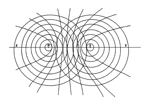
FIGURE 10.30 Hyperbolic patterns of two interacting radio waves propagated in opposite directions. These lines represent the locus of all points of a specified time difference between master and secondary pulses. The straight-line MS is called the baseline. The maximum distance of the target object should not exceed 6 times the length of the baseline
considered accurate only to within ±2°; for example, under 200 km (120 miles) to the transmitter in favourable conditions and ±5° to 10° when conditions are unfavourable.
Information on the locations, ranges, and using procedures of radio beacons are given in a number of publications such as DMAHTC Publication No. 117 The Radio Navigation Aids. Correct radio beacon bearings are plotted on Mercator charts for position estimation. Because of possible inaccuracies, radio beacons are not used universally. Navigators such as small boats and merchant ships not equipped with other systems use radio beacons.
Loran-C
Loran was developed in the 1940s to be one of the first systems implementing a long-range hyperbolic system for both ships and aircraft. The system used master and slave stations transmitting sequential radio waves in the upper MF band with frequencies between 1850 kHz and 1950 kHz. Loran-A featured ground wave coverage out to between 700 km and 1250 km from the baseline by day, and up to 2200 km by night. It was the most widely used electronic navigation system until 1970. Later, a system employing synchronized pulses for both time-difference and phase comparison measurements was developed, known as Loran-C. Loran-C was configured to operate in a chain form consisting of more than one slave station usually located in triangles.
All stations in the system transmit a signal on a common carrier frequency in mid-LF band of 100 kHz ± 10 kHz. The ground wave range is about 1900 km. One-hop sky waves have a range of about 3600 km, and two-hop signals were noted to have been received about 6250 km from the ground station. One-hop sky waves are produced both by day and by night, while two-hop sky waves are formed only at night. Present Loran-C chains have baseline distances between 1500 km and 2300 km. The accuracy of the system varies from about ±200 m rms near the baseline to ±600 m rms near the extreme ranges
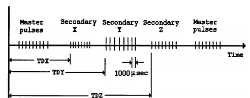
FIGURE 10.31 Loran-C pulse sequence. The nine pulses from the master station are separated by 1 ms intervals, except the ninth one, which has a 2 ms interval. The secondary stations X, Y, and Z transmit pulses sometime after they receive the information from the master station. The receivers picking up these pulses provide direct latitude and longitude information, usually by a digital readout.
of the system. Differential techniques employed in recent years have increased the accuracy. The low frequency and high-power transmitters allow ground waves to penetrate the surface layer of the sea water, enabling submerged submarines to receive them.
To lessen the large power requirements, multi pulsed signals are used. The multi pulsed signals of each master station and its associated secondary stations are transmitted in a predetermined sequence, as shown in Figure 10.31. Eight of the nine pulses are separated by 1 ms intervals and the ninth one by a 2-ms interval. Integrated master and secondary pulses are compared at a sampling point at exactly 30 µs from their leading edges.
Loran-C receivers are fully automatic, suitable to be employed for marine, land vehicle, and aircraft applications. Most receivers provide direct lat/long digital readout, precise to a tenth of a minute of arc.
They also provide auxiliary features such as destination selection, course and speed over ground, etc. Once initialized, they automatically select the best chain and the most suitable master/secondary pulses. There are 13 Loran-C chains worldwide. Each chain uses a different basic pulse repetition rate (PRR) and pulse repetition interval (PRI). The specific PRI used in a given chain is referred to as group repetition interval (GRI), often called rate. This system has enjoyed great expansion since 1970s, attracting many users. It has found applications in ships, aircraft, as well as land vehicles. Land vehicles are equipped with automatic vehicle location systems (AVLS). In one application in the U.S., the AVLS system is integrated with the city’s emergency telephone system, a computer-aided dispatch system to control the position of emergency vehicles such as ambulances and fire trucks. Nevertheless, the progress made in satellite-based global positioning systems (GPS) calls for termination of Loran-C in the very near future. However, complete system shut-down may not occur immediately, due to the vast number of current users of the system.
Decca
Decca is similar to Loran-C in that each chain is composed of one master and three slave stations arranged in star pattern, at an angle of about 120° between the baselines. It uses unmodulated continuous waves rather than the pulsed waves of Loran. The characteristic hyperbolic grid pattern is formed by phase comparisons of master and slave signals. All stations transmit in the LF-band between 70 kHz and 130 kHz. The nominal range is about 400 km both by day and by night. The system is extremely accurate within the operating range. The signals transmitted by each of the stations are all harmonics of a single fundamental frequency.
There are a wide variety of receivers available for Decca system, including automatic flight logs for aircraft. In general, the systems consist of four separate receivers, each of which can be set to receive one of the four signals transmitted by a given chain. The lane identification is accomplished by a signal transmitted by each master and slave station, transmitted once every 20 s for a duration of 0.6 s. By some
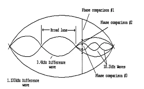
FIGURE 10.32 Three successive phase comparisons for lane resolution in Omega systems. Phase differences are compared in three stages with respect to three different signals transmitted by each station for accurate position finding. One wavelength is 25 km, representing two lanes. Accuracy of the Omega system is limited.
short signal interruptions and transmissions of harmonics simultaneously, zones and lanes are identified in a precise manner.
Consol
Consol is limited to the Eastern and Northern Atlantics. It is a hyperbolic system with extremely short baseline lengths, such that a collapsed hyperbolic pattern is formed. It employs three towers located three wavelengths apart. The operational frequencies are in the MF range between 250 kHz and 370 kHz. The system range is about 1900 km by day and 2400 km by night. The minimum range is about 40 km near the stations. One tower transmits a continuous wave, while other towers transmit waves with 180° phase shift by a keying cycle. The signals are modulated by dots and dashes such that receivers determine the position by counting them and printing on Consol grid patterns.
Omega
Omega is a hyperbolic navigation system that covers the entire world with only eight transmission stations located 7500 km to 9500 km apart. It transmits on frequencies in the VLF band from 10 kHz to 14 kHz at a power of 10 kW. The signals of at least three and usually four stations can be received at any position on Earth.
The 10 kHz to 14 kHz frequency band was chosen specifically to take advantage of several favorable propagation characteristics, such as: (1) to use the Earth’s surface and ionosphere as a waveguide; (2) to enable submerged submarines to receive the signals; and (3) to form long baselines at 7500 km to 9500 km. The basic frequency at which all eight stations transmit is 10.2 kHz. Each station transmits four navigation signals as well as a timing signal with atomic frequency standards ensuring that all stations are kept exactly in phase. Two continuous waves are in phase but traveling in opposite directions to produce a series of Omega lanes. Within each lane, a phase difference measurement would progress from 0° to 360° as the receiver moves across, as shown in Figure 10.32. Two Omega lanes complete one cycle, giving a wavelength of 25 km and lane of 12 km expanding as the distance from the baseline increases. Lanes are identified by three other signals transmitted by each station on a multiplexed basis. Omega
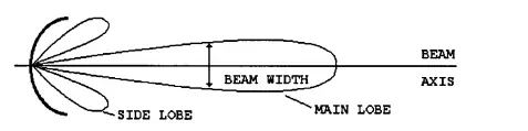
FIGURE 10.33 A surface search radar beam. High-frequency electromagnetic waves are formed by parabolic antenna. The receiving antenna is rotated 360° to scan the entire surrounding area. The location of the target is determined by the reflected back signals and the orientation of the antenna
fixes have been accurate to within ±1.5 km rms by day and ±3 km rms by night. Differential techniques can greatly reduce this error. Omega receivers are fully automated sets that provide direct lat/long readout for a cost of around U.S. $1,000 for marine and aviation use. Nevertheless, since the precision of the system is not as good as others, they are mainly used as back-up systems.
Radar
The word is derived from radio detection and ranging. It works on the basic principle of reflection, which determines the time required for an RF pulse to travel from a reference source to a target and return as an echo. Most surface search and navigation radar high-frequency electromagnetic waves are formed by a parabolic antenna into a beam form, as shown in Figure 10.33. The receiving antenna is rotated to scan the entire surrounding area, and the bearings to the target are determined by the orientation of the antenna at the moment the echo returns. A standard radar is made up of five components: transmitter, modulator, antenna, receiver, and indicator. They operate on pulse modulation.
Radars are extremely important devices for air control applications. Nowadays, airborne beacon radar systems are well developed in traffic alert and collision avoidance systems (TCAS). In this system, each plane constantly emits an interrogation signal, which is received by all nearby aircraft that are equipped appropriately. The signal triggers a transponder in the target aircraft, which then transmits some information concerning 3-D location and identification.


Comments are closed.