There are two broad categories: (1) mechanical gyroscopes and (2) optical gyroscopes. Within both of these categories, there are many different types available. Only the few basic types will be described to
illustrate the operating principles; detailed information may be found in the references listed at the end of this chapter.
Mechanical gyroscopes: The first mechanical gyroscope was built by Foucault in 1852, as a gimbaled wheel that stayed fixed in space due to angular momentum while the platform rotated around it. They operate on the basis of conservation of angular momentum by sensing the change in direction of an angular momentum. There are many different types, which are:
1. Single degree of freedom gyroscopes: include the rate, rate integrating, spinning rotor flywheel, electron, and particle gyros.
2. Two degree of freedom gyroscopes: incorporate the external gimbal types, two-axis floated, spherical free-rotor, electrically suspended, gas-bearing free-rotor gyros.
3. Vibrating gyroscopes: include the tuning fork, vibrating string, vibrating shell, hemispherical resonating, and vibrating cylinder gyros.
4. Continuous linear momentum gyroscopes: incorporate a steady stream of fluid, plasma, or electrons, which tends to maintain its established velocity vector as the platform turns. One typical example is based on a differential pair of hot-wire anemometers to detect the apparent lateral displacement of the flowing air column.
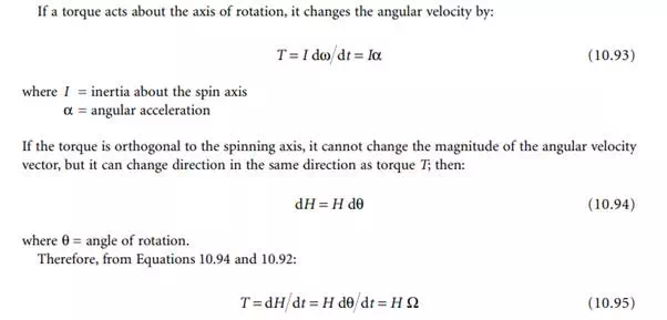
The operating principle of all mechanical gyroscopes is based on the conservation of angular momentum, as shown in Figure 10.20. The angular momentum is important since it provides an axis of reference. From Newton’s second law, the angular momentum of a body will remain unchanged unless it is acted upon by a torque. The rate of change of angular momentum is equal to the magnitude of the torque, in vectorial form as:
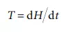
where H = angular momentum (= inertia × angular velocity, Iω).
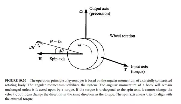
where Ω is the precession rate or the angular velocity of the spinning wheel about the axis normal to the plane of the spin and the input torque. Generally, the spin axis tries to align with the external input torque. These equations can be elaborated to describe the operating principles of mechanical gyros by taking into account the angular momentum in x, y, and z directions, nutation, coriolis accelerations, directions of other influencing torques and linear forces, etc. Here, the operation of the well-known flywheel gyroscope will be described as the basis for further discussions on inertial navigation systems.
An example of a double-axis flywheel gyro is shown in Figure 10.21. In this type of gyroscope, an electrically driven rotor is suspended in a pair of precision low-friction bearings at both ends of the rotor axle. The rotor bearings are supported by a circular ring known as an inner gimbal ring, which in turn pivots on a second set of bearings that is attached to the outer gimbal ring. The pivoting action of the inner gimbal defines the horizontal axis of the gyro, which is perpendicular to the spin axis of the rotor. The outer gimbal ring is attached to the instrument frame by a third set of bearings that defines the vertical axis of the gyro that is perpendicular to both the horizontal axis and the spin axis. This type of
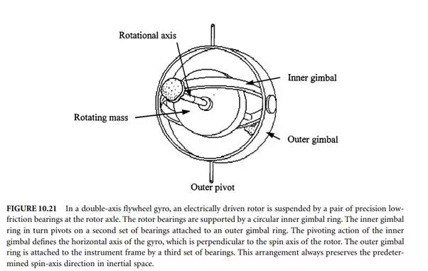
suspension has the property of always preserving the predetermined spin-axis direction in inertial space. Equations governing the two degrees of freedom gyroscope can be written using Equations 10.92 to 10.95. The torque with respect to an inertial reference frame can be expressed as:
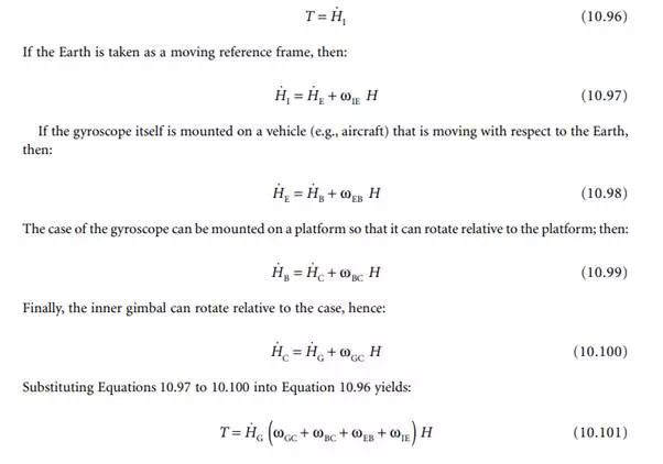
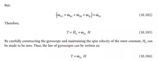
This means that if an external torque T is applied to the gyroscope, the inner gimbal will process with respect to the inertial frame with a velocity ω such that Equation 10.104 is satisfied. In most designs (e.g., rate gyros), the gimbal is hermetically sealed in a liquid and liquid is floated in the case, to unload the gimbal bearings and to provide viscous damping. A pick-off senses gimbal deflection by means of position transducers and it controls a servo system, with a servomotor driving the case to maintain pick-off null.
Optical gyroscopes are based on the inertial properties of light instead of Newton’s law of motion. They operate on the Sagnac effect, which produces interferometer fringe shift against the rotation rate. In this case, two light waves circulate in opposite directions around a path of radius R, beginning at source S. A typical arrangement for the illustration of operation principles is shown in Figure 10.22. When the gyro is stationary, the two beams arrive at the detector at the same time and no phase difference will be recorded. Assume that the source is rotating with a velocity ω so that light traveling in the opposite direction to rotation returns to the source sooner than that traveling in the same direction. Thus, any rotation of the system about the spin axis causes the distance covered by the beam traveling in the direction of rotation to lengthen, and the distance travelled by the beam in the opposite direction to shorten. The two beams interfere to form a fringe pattern and the fringe position may be recorded, or the phase differences of the two beams may be sensed. This phase difference is directional and proportional to the angular velocity. Usually, photodetectors are used to measure the phase shift.
Two different types of optical gyros can be categorized: either passive or active, and resonant or no resonant. In passive gyro sensors, the Sagnac phase is measured by some external means; whereas in active gyros, the Sagnac phase causes a frequency change internal to the gyro that is directly proportional to the rotation rate.
The Sagnac interferometer is the basis of the interferometric fiber-optic gyro (IFOG). A typical fibreoptic gyroscope is shown in Figure 10.22. However, the most widely used gyro is the active resonant ring laser gyro (RLG), which is applied extensively in aircraft navigation. Two different types of resonant passive gyros, the resonant fiber-optic gyro (RFOG) and the micro-optic gyro (MOG), are lower cost devices commonly used and comparable to RLGs.