Errors
In general, inertial navigation is an initial value process in which the location of the navigating object is determined by adding distances moved in known directions. Any errors in the system cause misrepresentation of the desired location by being off-target. The major disadvantage of an inertial guidance system is that its errors tend to grow with time. These errors in the deduced location are due to a number of reasons, including: imperfect knowledge of the starting conditions, errors in computation, and mainly errors generated by gyros and accelerometers.
If the error build-up with time becomes too large, external aids (e.g., LORAN, OMEGA) may be used to reset or update the system. Optimal use of the data from external aids must account for the geometry of the update and also for the accuracy of the update relative to the accuracy of the inertial system. The Kalman filter, for example, is one of the computational procedures frequently applied for optimally combining data from different sources.
Errors can broadly be classified as:
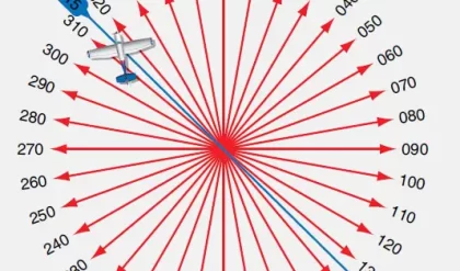
1. System heading error: A misalignment angle in the heading of an object traveling with a velocity can cause serious errors. For example, a vehicle traveling with velocity of 500 km h–1 in the same direction with 0.1° initial heading error will be off the target by approximately 873 m at the end of 1 h travel.
2. Scale error: Error in scaling can accumulate. In order to minimize scale errors, a scale factor is used. The scale factor is the ratio between changes in the input and output signals. It simply translates the gyro output (counts per second in the case of RLG) into a corresponding angle rotation. Some instruments may have different scale factors for positive and negative inputs, known as scale factor asymmetry. (Scale factors are measured in ° h–1 mA–1, ° h–1 Hz–1, or g Hz–1.)
3. Nonlinearity and composite errors: In most cases, scale factors are not constant, but they can have second- or higher-order terms relating the output signals to the input. Statistical techniques can be employed to minimize these errors.
4. Bias errors: Zero offset or bias error is due to existence of some level of output signal for a zero input. Bias errors exist in accelerometers, gyros, tilt misalignments, etc.
5. Random drift and random walk errors: In some cases, the outputs of the devices can change due to disturbances inside the sensors, such as ball bearing noise in mechanical gyros. These disturbances may be related to temperature changes, aging, etc. White noise in optical gyros can cause a long-term accumulation in angle error known as the random walk.
6. Dead band, threshold, resolution, and hysteresis errors: These errors can be related to inherent operation of accelerometers and gyros. They can be due to stiction, minimum input required for an output, minimum measurable outputs, and non-repeatability of variations in the output versus variations in the input.
It should be pointed out that this list is by no means exhaustive. Detailed error analysis can be found in the references cited.
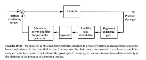
Stabilization
The inertial navigation sensors must maintain angles within specified limits in spite of the disturbances imposed by the moving object. Accuracy requirements demand that the system must provide reliable and stable information in spite vibrations and other disturbing factors. One way of achieving stabilization is by using a stabilized platform. These platforms are designed to maintain accelerometers and gyros accurately levelled and oriented in the azimuth direction. In some cases, the platform is driven around its axis by servo amplifiers and electric motors. Usually, outputs of doubly integrating accelerometers are used directly to control the level-axis gyroscope precession rates. Sensitive pick-offs on the gyroscopes fed error signals are used to maintain a desired stable platform in the face of disturbing torques. The operation of a typical system, in block diagram form, is shown in Figure 10.24.
Unlike platform models, in a strapped-down system, gyroscopes and accelerometers are rigidly mounted to the vehicle structure so that they move with the vehicle. The accelerometers and gyroscopes are manufactured to measure accelerations and angles up to the maximum expected values. As the vehicle travels, the measured values are frequently transmitted to a computer. The computer uses these values to resolve the readings into the navigation axis sets and make deductions on the body axis sets.


Comments are closed.