Halit Eren and C. C. Fung Modern electronic navigation systems can be classified by range, scope, error, and cost. The range classifications are short, medium, and long ranges, within which exact limits are rather indefinite. The scope classifications can be either self-contained or externally supported, and active (transmitting) or passive (not transmitting) mode of operation.
Short-range systems include radio beacons, radar, and Decca. Medium-range systems include Decca and certain types of extended-range radars. The long-range systems include Loran-C, Consol, and Omega. All these systems depend on active radio frequency (RF) transmissions, and all are externally supported with respect to the object being navigated, with the exception of the radar. In addition to these, there is another category of systems which are called advanced navigation systems; the transit satellite navigation systems, Glonass, and the Global Positioning Systems (GPS) are typical examples.
Utilization of electromagnetic radio waves is common to all navigation systems discussed here. Understanding of their behavior in the Earth’s atmosphere is very important in the design, construction, and use of all kinds of navigation equipment — from satellites to simple hand-held receivers.
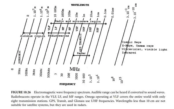
When an FM radio wave is generated within the Earth’s atmosphere, the wave travels outward. The waves may be absorbed or reflected from surfaces of materials they encounter. The absorption and scattering of electromagnetic waves take place for many reasons, one of which is caused by excitation of electrons within the molecules in the propagation media. The behavior of an electromagnetic wave is dependent on its frequency and corresponding wavelength. Figure 10.26 shows the frequency spectrum of electromagnetic waves. They are classified as audible waves at the lower end of the spectrum, radio waves from 5 kHz to 300 GHz, and visible light and various other types of rays at the upper end of the spectrum.
For practical purposes, the radio wave spectrum is broken into eight bands of frequencies; these are: very low frequency (VFL) less than 30 kHz, low frequency (LF) 30 kHz to 300 kHz, medium frequency (MF) 300 kHz to 3 MHz, high frequency (HF) 3 MHz to 30 MHz, very high frequency (VHF) 30 MHz to 300 MHz, ultra high frequency (UHF) 300 MHz to 3 GHz, super high frequency (SHF) 3 GHz to 30 GHz, and extremely high frequency (EHF) 30 GHz to 300 GHz.
For easy identification, the frequencies above 1 GHz are further broken down by letter designators, as: L-band (1–2 GHz), S-band (2–4 GHz), C-band (4–8 GHz), X-band (8–12.5 GHz), and K-band (12.5–40 GHz). Since severe absorption of radar waves occurs near the resonant frequency of water vapor at 22.2 GHz, the K-band is subdivided into lower K-band (12.5–18 GHz) and upper K-band (26.5–40 GHz). Most navigation radars operate in the X- and S-bands, and many weapons fire control radars operate in the K-band range
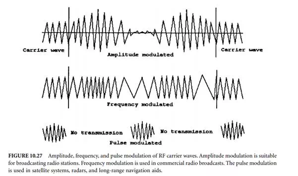
The radio waves are transmitted as continuous or modulated waves. A carrier wave (CW) is modulated to convey information in three basic forms: amplitude, frequency, and pulse modulation, as shown in Figure 10.27. The amplitude modulation (AM) modifies the amplitude of the carrier wave with a modulating signal. In frequency modulation (FM), the frequency of the carrier wave is altered in accordance with the frequency of the modulating wave. FM is used in commercial radio broadcasts and the sound
portion of the television broadcast. Pulse modulation is different from AM and FM in that there is usually no impressed modulation wave employed. In this modulation, the continuous wave is broken up into very short bursts or “pulses,” separated by periods of silence during which no wave is transmitted. This is used in satellite navigation systems, surface search radars, and long-range radio navigation aids such as Loran.
When an electromagnetic wave encounters an obstruction, diffraction takes place marked by a weak reception of the signal within the “shadow” zone. Two waves acting on the same point will also result in interference. The degree of interference depends on the phase and frequency relationship. For example, two waves of the same frequency with a 180° phase difference will result in a null at that point. Also, under certain conditions, a portion of the electromagnetic energy in radio waves may reflect back toward the Earth’s surface to form the ionosphere. The ionosphere is a layer of charged particles located about 90 to 400 km high from Earth’s surface; such reflected waves are called sky waves.
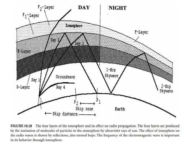
In the study of radio wave propagation, there are four ionosphere layers of importance, as shown in Figure 10.28. The D-layer is located about 60 km to 90 km and is formed during daylight. The E-layer is about 110 km. It persists through the night with decreased intensity. The F1-layer is between 175 km and 200 km; it occurs only during daylight. The F2-layer is between 250 km and 400 km; its strength is greatest in the day but it combines with the F1-layer later to form a weak F-layer after dark. The layers in the ionosphere are variable, with the pattern seeming to have diurnal, seasonal, and sun spot periods. The layers may be highly conductive or may entirely hinder transmissions, depending on the frequency of the wave, its angle of incidence, height, and intensity on various layers at the time of transmission. In general, frequencies in the MF and HF bands are most suitable for ionosphere reflections during both day and night.
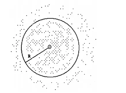
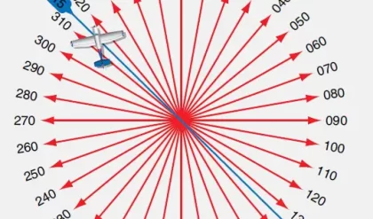
FIGURE 10.29 The rms radius circle that encompasses 68% of all measured positions. The variations in the measurements are due to a number of factors, including: ionosphere conditions, precise location of satellites, and inefficiencies in electronic circuits. (2 rms encompasses 95% of all indicated positions.)
Because of the higher resistance of the Earth’s crust as compared to the atmosphere, the lower portions of radio waves parallel to the Earth’s surface are slowed down, causing the waves to bend toward Earth. A wave of this type is termed a ground wave. The ground waves exist because they use the Earth’s surface as a conductor. They occur at low frequency since LF causes more bending in conformity to Earth’s shape. The ultimate range of such ground waves depends on the absorption effects. Sometimes, in the lower atmosphere, surface ducting occurs by multiple hopping, thus extending the range of a ground wave well beyond its normal limits. It is associated with higher radio and radar frequencies. This phenomenon is common in tropical latitudes. Behavior patterns of waves transmitted at various angles are illustrated in Figure 10.28.


Comments are closed.