The length scale of a displacement interferometer that is operated in ambient air is given by λA = λV/nA, where λA is the wavelength of the source in air, λV is the wavelength in vacuum and nA is the refractive index of air. The vacuum wavelength λV is related to the speed of light by λV = c/f0. The constant c, the speed of light in vacuum, was redefined in 1983 [1]. It is now defined to be exactly c = 299,792,458 m s–1.
Thus, in order to measure distances interferometrically, it is essential to know the refractive index of air with an accuracy that is not less than the stability and the degree of certainty of the vacuum wavelength of the light source.
According to Edlén [7, 8] and Owens[9], the refractive index is a function of the atmospheric pressure P, the temperature T, the relative humidity H, or alternatively the partial pressure of the water vapor in air es , and the carbon dioxide concentration by volume D. The standard composition by volume of dry air is given by 78.03% N2, 20.99% O2, 0.933% Ar, 0.035% CO2, and some other trace components, mainly noble gases [10]. The only component of the above list that might have a variability is CO2, which follows a long-term increasing behavior presumably associated with the combustion of fossil fuel [11]. The current value is ≈350 ppm by volume and is increasing by ≈1.4 ppm per year. The CO2 concentration in air can also change in an industrial environment due to CO2 emitters and can therefore show significant local variations.
More recently, dependencies of the refractive index on non-natural gaseous compounds like hydrocarbons in the air have been published [12] as well as corrections to Edlén’s formulations [13–15]. Corrections to the refractive index due to those compounds may be necessary for very high-precision measurements in an industrial environment where chemical solvents or oils are in use. In Table 6.9, some non-natural compounds, their maximum workplace concentrations, and their effect on the refractive index if present at the location of the interferometer are listed.
Jones [16] combined a precise determination of the density of moist air with Edlén’s formulation to yield a somewhat simpler representation. For a typical iodine-stabilized He–Ne laser that has a vacuum wavelength of λV = 632.9913 nm, the Jones formulation is given by [17]:
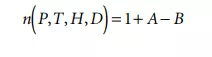
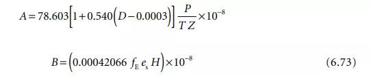
In Equation 6.73, P is the atmospheric pressure in pascals, T is the absolute temperature in kelvin, H is the relative humidity in %, and D is the concentration of CO2 in percent by volume. There are three additional factors in Jones’ formulation that take the nonideal behavior of moist air as compared to an ideal gas into account. They are Z, a compressibility factor that reflects the nonideality of the air–water vapor mixture and which, for air containing reasonable amounts of CO2 at a temperature between 15°C and 28°C and pressure of between 7 × 10⁴ Pa and 11 × 104 Pa, lies in the range between 0.99949 and 0.99979. fE is an enhancement factor that expresses the fact that the effective saturation vapor pressure of water in air is greater than the saturation vapor pressure es. For the pressure and temperature ranges given above, fE is bounded between 1.0030 and 1.0046 [16]. es is the saturation vapor pressure over a plane surface of pure liquid water and according to Jones is about 1705 Pa at a temperature of 15.0°C and about 3779 Pa for 28.0°C. Tables of Z, fE and es are included in the Appendix of Jones’ paper [16].
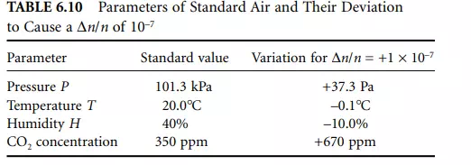
Table 6.10 gives an overview of the changes in environmental parameters that would cause a relative index change of 10^–7.
Edlén [8] and Jones [16] estimate that their empirical expressions for the dependency of the refractive index of air on the listed parameters has an absolute uncertainty of 5 × 10^–8.
Besides this fundamental limitation, there are some practical considerations that must be taken into account regarding the precision with which the environmental parameters can be measured. Estler [17] states that atmospheric pressure P can currently be determined with an uncertainty of ≈2.7 Pa, which can be assumed to be constant for the entire optical path of the interferometer if it is oriented horizontally. Please note that at sea level, the pressure gradient is ≈–13 Pa m–1, resulting in a pressure-induced change in nA of 3.4 × 10⁻⁸ m–1 if the measuring equipment is not kept level.
In an exceptionally well-controlled laboratory environment where special care is devoted to keep temperature gradients from affecting the refractive index along the optical path as much as possible, uncertainties of the temperature measurement can be as low as 0.01°C according to [17]. Humidity measured with high accuracy dew-point hygrometers can have uncertainties down to 0.5%. Changes in carbon dioxide concentrations have to be very significant (20% of the natural concentration) to cause a ∆n/n of 10^–8.
Michelson Interferometer
The basis for most interferometers used in interferometric dimensional gages is the classical Michelson interferometer [4] which is shown in Figure 6.49. The coherent monochromatic light of a wavelength stabilized He–Ne laser is incident onto a beam splitter which splits the light into two equally intense beams (1) and (2).
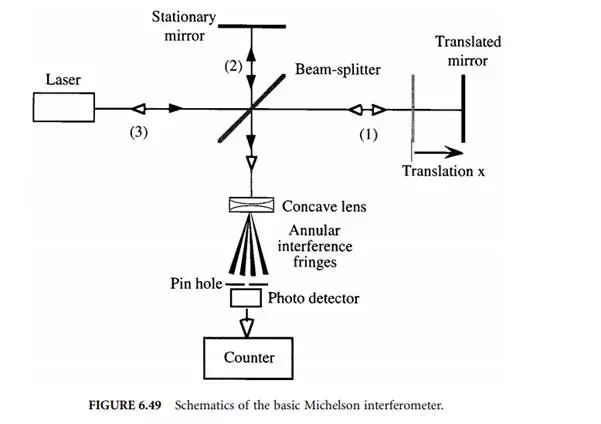
They are reflected off of both the stationary and the translatable mirror whose displacement x is to be measured, and recombined at the splitter, where they are redirected toward a concave lens. Due to the coherence of the laser light, the wavefronts have a well-defined phase relation with respect to each other. This phase is determined by the difference between the optical path lengths of the two beams in arms 1 and 2. If this path difference is continuously changed by translating one of the mirrors, a sinusoidal intensity variation can be observed at a fixed location in space behind the lens used to introduce a beam divergence, resulting in an annular fringe pattern. The pinhole is used to define an exact location of observation and the photodetector picks up the varying intensity for further processing. In the most basic signal processing setup, the number of bright and dark cycles are fed into a counter, which then counts changes in optical path length in integer multiples of λA/2. More sophisticated signal processing not only counts cycles but also determines relative phase changes in the sinusoidal varying intensity so that resolutions of λA/512 can ultimately be achieved.
When moving the mirror, one must guarantee a smooth motion without backward jitter of the mirror carriage to avoid double counts of interference fringes. Very high-quality linear bearings (such as air bearings) are necessary to accomplish just that.
As can be seen in Figure 6.49, the light reflected off both mirrors essentially retraces its own path and is at least partially incident onto the active volume of the laser source (3), thereby forming an external laser resonator which is able to detune the laser, effectively modulating its output power as well as its wavelength. To avoid this effect, commercial versions of Michelson interferometers employ corner-cube reflectors instead of plane mirrors as well as optical isolators, as shown in Figures 6.50 and 6.51. Some authors, however, report using optical arrangements that utilize this effect in conjunction with laser diodes to realize low-cost, short-travel displacement


Comments are closed.