The detection of angular and linear motion is a key function in a multitude of systems such as machine tools, industrial robots, a variety of instruments, computer mice, etc. Although they are one of many techniques capable of such measurements, the ease with which they are interfaced to digital systems has made them very popular.
Optical encoders are used to measure either angular or linear positions. Those used for angular detection are commonly called rotary or shaft encoders, since they usually detect the rotation of a shaft. Optical encoders encompass a variety of devices, all of which use light as the means to transform movement into electrical signals. All devices have two basic building blocks: a main grating and a detection system. It is the position of one with respect to the other that is detected. The main grating represents the measurement standard. For linear measurements, the main grating, commonly called the scale, is one or more sets of parallel lines of constant or specially coded pitch supported by a substrate. Similarly, a rotary encoder has a grating with radial lines on a disk.
Both linear and rotary encoders can, in principle, be absolute or incremental, although in practice, linear absolute encoders employing optical principles are quite uncommon and have drastically limited
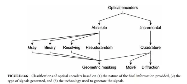
performance characteristics (accuracy, resolution, and/or maximum operating speed). Figure 6.66 shows a simplified classification of optical encoders. This classification refers to the nature of the information generated. The incremental encoder detects movement relative to a reference point. As a result, some form of reference signal is usually supplied by the encoder at a fixed position in order to define a reference position. The current position is then incremented (or decremented) as appropriate. Multiple reference marks can also be used, where the distance between successive marks is unique so that as soon as two successive marks have been detected, it becomes possible to establish absolute position from then on. The reference point can also be mechanical. Should power be lost, or a signal transmission error occur, then the absolute position is lost and the encoder must return to one or more reference points in order to reset its counters. Unfortunately, a loss of count may not be detected until a reference point is reaccessed. Furthermore, reading errors may accumulate. On the other hand, absolute encoders produce a set of binary signals from which the absolute position can be deduced without the knowledge of the previous motion history. The current position is known right from powering-on. In the case of absolute rotary encoders, single and multiturn devices are available. Multiturn devices use an internal mechanical transmission system to drive a second grating that serves as turn counter.
Most incremental encoders use quadrature signals as output to carry the motion information. Some encoders use one square-wave signal, which is used for position in one direction only. Also, this single square wave can be fed into either a PLC (programmable logic controller) or another electronic interface that converts this signal to a rate or RPM (revolution per minute) for speed indication. However, whenever bidirectional operation is required, quadrature signals are necessary. Quadrature signals come in analog or digital form. The analog form consists simply of a sine and a cosine signal. The number of sinusoidal cycles per unit change of the measured variable (a revolution or 360° for a rotary encoder) determines the basic resolution of the encoder prior to interpolation. The digital form consists of two square-wave trains, 90° (often called electrical degree) out of phase. The 90° phase lag is indispensable in order to detect the motion direction and hence increment or decrement the position counter accordingly. The main optical techniques to generate the quadrature signals are geometric masking, Moiré fringes, and diffraction based. For linear encoders, the basic resolution is related to the distance travelled by the grating in order for the encoder to produce one full quadrature cycle. For rotary encoders, the basic resolution is usually described as the number of quadrature cycles per turn. The resolution of an encoder system can be increased by electronic means. With analog quadrature signals, it is possible to interpolate within each quadrature cycle. The limit of the interpolation factor depends on the quality (mark space, quadrature separation, and jitter) of the basic signals. With square-wave signals, multiplication by a factor of two or four is easily achieved. Increasing the resolution in this manner does not, however, improve the trueness, often called accuracy (or linearity) of the measurement.
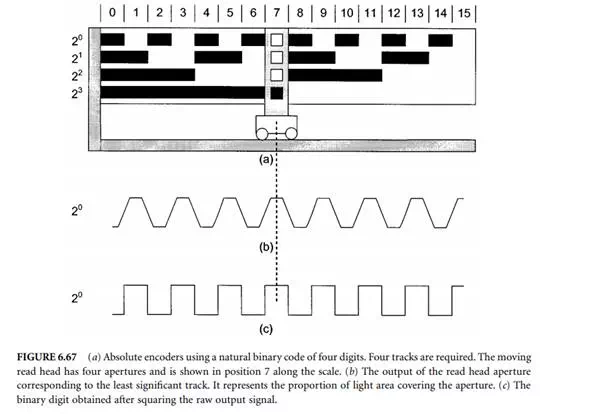
Absolute encoders are classified according to the type of code used. The main four codes are Gray, binary (usually read by vee-scan detection), optical resolving, and pseudorandom. All absolute encoders use geometric masking to generate the code.