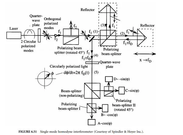
Figure 6.50 shows the commercially available two-frequency Michelson interferometer operating with a Zeeman-stabilized He–Ne laser source. This laser emits two longitudinal modes with frequencies f1 and f2 that are both circularly polarized in opposite directions. By passing the modes through a quarter-wave
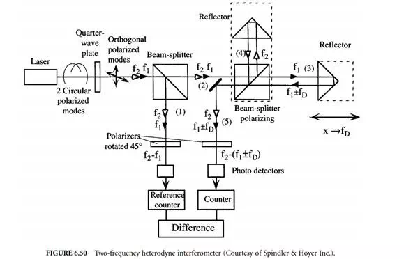
plate, two orthogonal linearly polarized waves are generated. Both are split by a nonpolarizing beam splitter. There is a polarizer located in arm 1 of that splitter, which is rotated by 45° with respect to both polarized waves impingng on it, thus effectively allowing them to interfere behind it yielding a difference frequency of f2 – f1 that is picked up by a photodetector and counted by a reference counter (frequency difference typically 1.5 MHz).
The orthogonal polarized waves in 2 are further split by a polarizing splitter. Spectral component f1 < f2 is transmitted into measuring arm 3 and frequency component f2 is reflected into reference arm 4 of the interferometer. Due to the velocity v of the reflector in arm 3 resulting in a displacement x, the frequency f1 is Doppler-shifted by fD (Equation 6.74). Movement of the reflector toward the interferometer results in a positive Doppler frequency fD > 0. After recombining both waves from 3 and 4 in the beam splitter again, they are sent through a polarizer in arm 5 that also is rotated by 45° with respect to the direction of polarization of both recombined waves, thereby allowing them to interfere, yielding a difference frequency of f2 – f1 – fD at the location of the photodetector, which is counted by a second counter. By continuously forming the difference of both counts, the measurand (the displacement of x in multiples of λA/2) is calculated.
With this type of interferometer, the direction of motion is given by the sign of the resulting count. One disadvantage of the two-mode heterodyne interferometer is its limited dynamic range for the velocity v of the reflector moving toward the interferometer, since the Doppler frequency fD, given by:
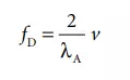
is bound to be less than the initial frequency difference between f2 and f1 for stationary reflectors. Given a typical Zeeman effect-induced frequency difference fz of 1.5 MHz, the velocity v is therefore bound to be less than:
There is no such bound if the reflector is traveling away from the interferometer. By electronically interpolating the output signal of the photodetector, subwavelength resolution can be obtained [22].