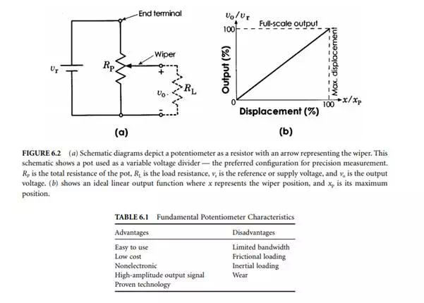
Resistive displacement sensors are commonly termed potentiometers or “pots.” A pot is an electromechanical device containing an electrically conductive wiper that slides against a fixed resistive element according to the position or angle of an external shaft. See Figure 6.1. Electrically, the resistive element is “divided” at the point of wiper contact. To measure displacement, a pot is typically wired in a “voltage divider” configuration, as shown in Figure 6.2. The circuit’s output, a function of the wiper’s position, is an analog voltage available for direct use or digitization. Calibration maps the output voltage to units of displacement.
Table 6.1 lists some attributes inherent to pots. This chapter describes the different types of pots available, their electrical and mechanical characteristics, and practical approaches to using them for precision measurement. Sources and typical prices are also discussed. Versatile, inexpensive, and easy to-use, pots are a popular choice for precision measurement.
Precision Potentiometers
Pots are available in great variety, with specific kinds optimized for specific applications. Position measurement requires a high-quality pot designed for extended operation. Avoid pots classified as trimmers, rheostats, attenuators, volume controls, panel controls, etc. Instead, look for precision potentiometers

Types of Precision Potentiometers
Precision pots are available in rotary, linear-motion, and string pot forms. String pots — also called cable pots, yo-yo pots, cable extension transducers, and draw wire transducers — measure the extended length of a spring-loaded cable. Rotary pots are available with single- or multiturn abilities: commonly 3, 5, or 10 turns. Linear-motion pots are available with maximum strokes ranging from roughly 5 mm to over 4 m [1, 2]. String pots are available with maximum extensions exceeding 50 m [3]. Pot manufacturers usually specify a pot’s type, dimensions, resistive element composition, electrical and mechanical parameters, and mounting method.
Resistive Element
Broadly, a pot’s resistive element can be classified as either wire wound, or non-wire wound. Wire wound elements contain tight coils of resistive wire that quantize measurement in step-like increments. In contrast, non-wire wound elements present a continuous sheet of resistive material capable of essentially unlimited measurement resolution.
Wire wound elements offer excellent temperature stability and high-power dissipation abilities. The coils quantize measurement according to wire size and spacing. Providing the resolution limits are acceptable, wire wound elements can be a satisfactory choice for precision measurement; however, conductive plastic or hybrid elements will usually perform better and for considerably more cycles. These and other popular non-wire wound elements are described in more detail below.
Conductive plastic elements feature a smooth film with unlimited resolution, low friction, low noise, and long operational life. They are sensitive to temperature and other environmental factors and their power dissipation abilities are low; however, they are an excellent choice for most precision measurement applications.

Hybrid elements feature a wire wound core with a conductive plastic coating, combining wire wound and conductive plastic technologies to realize some of the more desirable attributes of both. The plastic limits power dissipation abilities in exchange for low noise, long life, and unlimited resolution. Like wire wounds, hybrids offer excellent temperature stability. They make an excellent choice for precision measurement.
Cermet elements, made from a ceramic-metal alloy, offer unlimited resolution and reasonable noise levels. Their advantages include high power dissipation abilities and excellent stability in adverse conditions. Cermet elements are rarely applied to precision measurement because conductive plastic elements offer lower noise, lower friction, and longer life.
Carbon composition elements, molded under pressure from a carbon–plastic mixture, are inexpensive and very popular for general use, but not for precision measurement. They offer unlimited resolution and low noise, but are sensitive to environmental stresses (e.g., temperature, humidity) and are subject to wear.
Table 6.2 summarizes the distinguishing characteristics of the preferred resistive elements for precision measurement.
Electrical Characteristics
Before selecting a pot and integrating it into a measurement system, the following electrical characteristics should be considered.
Terminals and Taps
Table 6.3 shows the conventional markings found on the pot housing [4, 5]; CW and CCW indicate clockwise and counter-clockwise rotation as seen from the front end. Soldering studs and eyelets, integral connectors, and flying leads are common means for electrical connection. In addition to the wiper and end terminals, a pot may possess one or more terminals for taps. A tap enables an electrical connection to be made with a particular point along the resistive element. Sometimes, a shunt resistor is connected to a tap in order to modify the output function. End terminations and taps can exhibit different electrical characteristics depending on how they are manufactured. See [2] for more details.
Taper Pots are available in a variety of different tapers that determine the shape of the output function. With a linear-taper pot, the output varies linearly with wiper motion, as shown in Figure 6.2. (Note that a pot with a linear taper should not be confused with a linear-motion pot, which is sometimes called a “linear pot.”) Linear-taper pots are the most commonly available, and are widely used in sensing and control
applications. Pots with nonlinear tapers (e.g., logarithmic, sine, cosine, tangent, square, cube) can also be useful, especially where computer control is not involved. Nonstandard tapers can be custom-manufactured or alternatively, certain types of output functions can be produced using shunt resistors, by combining outputs from ganged pots or by other means. (Refer to [6, 7] for more details.) Of course, if a computer is involved, the output function can always be altered through a software lookup table or mapping function.
Electrical Travel
Figure 6.2 shows how the ideal output of a pot changes with wiper position. In practice, there is a small region at both ends where output remains constant until the wiper hits a mechanical stop. Mechanical travel is the total motion range of the wiper, and electrical travel is the slightly smaller motion range over which the electrical output is “valid.” Thus, when using a pot as a sensor, it is important to ensure that the wiper motion falls within the electrical travel limits.
Linearity
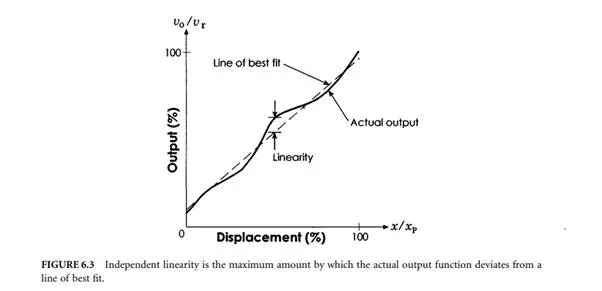
Linearity is the maximum deviation of the output function from an ideal straight line. Independent linearity is commonly specified, where the straight line is defined as the line that minimizes the linearity error over a series of sampled points, not necessarily measured over the full range of the pot. See Figure 6.3. Other linearity metrics, such as terminal-based linearity, absolute linearity, and zero-based linearity, are also sometimes used. Refer to [8] for more details. Pots are commonly available with independent linearities ranging from under 0.1% to 1%. When dealing with nonlinear output functions, conformity is specified since it is the more general term used to describe deviation from any ideal function. Conformity and linearity are usually expressed as a percentage of full-scale output (FSO).
Electrical Loading
Loading can significantly affect the linearity of measurements, regardless of a pot’s quality and construction. Consider an ideal linear pot connected to an infinite load impedance (i.e., as in Figure 6.2). Since no current flows through the load, the output changes perfectly linearly as the wiper travels along the length of the pot. However, if the load impedance is finite, the load draws some current, thereby affecting the output as illustrated in Figure 6.4. Circuit analysis shows that:
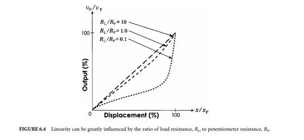

Therefore, RL/RP should be maximized to reduce loading effects (this also involves other trade-offs, to be discussed). A minimum RL/RP value of 10 is sometimes used as a guideline since loading error is then limited to under 1% of full-scale output. Also, some manufacturers recommend a minimum load impedance or maximum wiper current in order to minimize loading effects and prevent damage to the wiper contacts. The following are some additional strategies that can be taken:
· Use a regulated voltage source whose output is stable with load variations
· Use high input-impedance signal conditioning or data acquisition circuitry
· Use only a portion of the pot’s full travel
Resolution
Resolution defines the smallest possible change in output that can be produced and detected. In wire wound pots, the motion of the wiper over the coil generates a quantized response. Therefore, the best attainable resolution is r = (1/N) × 100%, where N is the number of turns in the coil. Non-wire wound pots produce a smooth response with essentially unlimited resolution. Hybrid pots also fall into this category. In practice, resolution is always limited by factors such as:
· Electrical noise, usually specified as noise for wire wound pots and smoothness for non-wire wound pots, both expressed as a percentage of full-scale output [10]
· Stability of the voltage supply, which can introduce additional noise into the measurement signal
· Analog-to-digital converter (ADC) resolution, usually expressed in “bits” (e.g., 10 mm travel digitized using a 12-bit ADC results in 10 mm/4096 = 0.0024 mm resolution at best)
· Mechanical effects such as stiction
Power Rating
The power dissipated by a pot is P = vr 2 /RP . Therefore, power rating determines the maximum voltage that can be applied to the pot at a given temperature. With greater voltage supplied to the pot, greater output (and noise) is produced but more power is dissipated, leading to greater thermal effects. In general, wire wound, and cermet pots are better able to dissipate heat, and thus have the highest power ratings.
Temperature Coefficient
As temperature increases, pot resistance also increases. However, a pot connected as shown in Figure 6.2 will divide the voltage equally well, regardless of its total resistance. Thus, temperature effects are not usually a major concern as long as the changes in resistance are uniform and the pot operates within its ratings. However, an increase in pot resistance also increases loading nonlinearities. Therefore, temperature coefficients can become an important consideration. The temperature coefficient, typically specified in ppm ˚C–1, can be expressed as α = (∆RP/RP)/∆t, where ∆t is the change in temperature and ∆RP is the corresponding change in total resistance. In general, wire wound pots possess the lowest temperature coefficients. Temperature-compensating signal-conditioning circuitry can also be used.
Resistance
Since a pot divides voltage equally well regardless of its total resistance, resistance tolerance is not usually a major concern. However, total resistance can have a great impact on loading effects. If resistance is large, less current flows through the pot, thus reducing temperature effects, but also increasing loading.
AC Excitation
Pots can operate using either a dc or an ac voltage source. However, wire wound pots are susceptible to capacitive and inductive effects that can be substantial at moderate to high frequencies.