In a large number of electronic circuits, we require DC voltage for operation. We can easily convert the AC voltage or AC current into DC voltage or DC current by using a device calledP-N junction diode. One of the most important applications of a P-N junction diode is the rectification ofAlternating Current (AC) into Direct Current (DC). A P-N junction diode allows electric current in only forward bias condition and blocks electric current in reverse bias condition. In simple words, a diode allows electric current in one direction. This unique property of the diode allows it to acts like a rectifier.
Rectifier definition
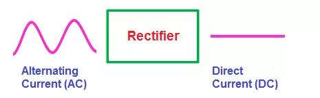
A rectifier is an electrical device that converts an Alternating Current (AC) into a Direct Current (DC) by using one or more P-N junction diodes.
What is a rectifier?
When the voltage is applied to the P-N junction diode in such a way that the positive terminal of the battery is connected to the p-type semiconductor and the negative terminal of the battery is connected to the n-type semiconductor, the diode is said to be forward biased. When this forward bias voltage is applied to the P-N junction diode, a large number of free electrons (majority carriers) in the n-type semiconductor experience a repulsive force from the negative terminal of the battery similarly a large number of holes (majority carriers) in the p-type semiconductor experience a repulsive force from the positive terminal of the battery.
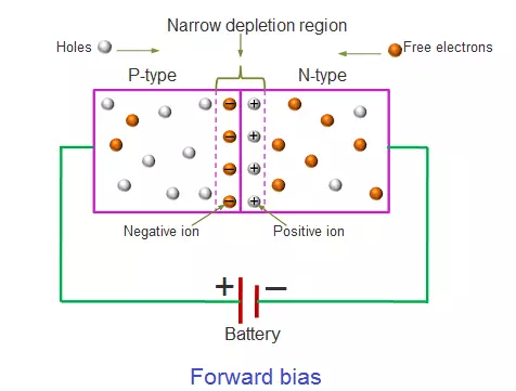
As a result, the free electrons in the n-type semiconductor start moving from n-side to p-side similarly the holes in the p-type semiconductor start moving from p-side to n-side. We know that electric current means the flow of charge carriers (free electrons and holes). Therefore, the flow of electrons from n-side to p-side and the flow of holes from p-side to n-side conduct electric current. The majority carriers produce the electric current in forward bias condition. So the electric current produced in forward bias condition is also known as majority current. When the voltage is applied to the P-N junction diode in such a way that the positive terminal of the battery is connected to the n-type semiconductor and the negative terminal of the battery is connected to the p-type semiconductor, the diode is said to be reverse biased. When this reverse bias voltage is applied to the P-N junction diode, a large number of free electrons (majority carriers) in the n-type semiconductor experience an attractive force from the positive terminal of the battery similarly a large number of holes (majority carriers) in the p-type semiconductor experience an attractive force from the negative terminal of the battery.
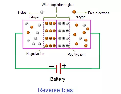
As a result, the free electrons (majority carriers) in the n-type semiconductor moves away from the P-N junction and attracted to the positive terminal of the battery similarly the holes (majority carriers) in the p-type semiconductor moves away from the P-N junction and attracted to the negative terminal of the battery. Therefore, the electric current flow does not occur across the P-N junction. However, the minority carriers (free electrons) in the p-type semiconductor experience a repulsive force from the negative terminal of the battery similarly the minority carriers (holes) in the n-type semiconductor experience a repulsive force from the positive terminal of the attery. As a result, the minority carriers free electrons in the p-type semiconductor and the minority carriers holes in the n-type semiconductor starts flowing across the junction. Thus, electric current is produced in the reverse bias diode due to the minority carriers. However, the electric current produced by the minority carriers is very small. So the minority carrier current in the reverse bias condition is neglected. Thus, the P-N junction diode allows electric current in forward bias condition and blocks electric current in reverse bias condition. In simple words, a P-N junction diode allows electric current in only one direction. This unique property of the diode allows it to acts like a rectifier. The forward bias and reverse bias voltage applied to the diode is nothing but a DC voltage. A DC voltage produces a current which always flows in one direction (either forward direction or backward direction).
But an AC voltage produces a current which always reverses its direction many times a second (forward to backward and backward to forward). We have observed how a diode behaves when DC voltage (forward bias voltage and reverse bias voltage) is applied to it. Now let’s take look at a P-N junction diode when AC voltage is applied to it.
The AC voltage or AC current is often represented by a sinusoidal waveform whereas the DC current is represented by a straight horizontal line. In the sinusoidal waveform, the upper half cycle represents the positive half cycle and the lower half cycle represents the negative half cycle. The positive half cycle of the AC voltage is analogous to the forward bias DC voltage and the negative half cycle of the AC voltage is analogous to the reverse bias DC voltage.
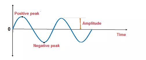
The alternating current starts from zero and grows to peak forward current or peak positive current. The positive peak of the sinusoidal waveform represents the maximum or peak forward current. After reaching the peak forward current, it starts decreasing and reaches to zero. After a short period, the alternating current starts increasing in the reverse or negative direction and grows to peak reverse current or peak negative current. The negative peak of the sinusoidal waveform represents the maximum or peak reverse current. After reaching the peak reverse current, it starts decreasing and reaches to zero. Likewise, the alternating current continuously changes its direction in a short period.
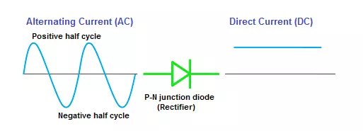
When AC voltage or AC current is applied across the P-N junction diode, during the positive half cycle the diode is forward biased and allows electric current through it. However, when the AC current reverses its direction to negative half cycle, the diode is reverse biased and does not allow electric current through it. In simple words, during the positive half cycle, the diode allows current and during the negative half cycle, the diode blocks current. Thus, electric current flows through the diode only during the positive half cycle of the AC current.
This current which flows across the diode is nothing but a DC current. Thus, the P-N junction diode acts like a rectifier by converting the AC current into DC current.
However, the DC current produced by a basic rectifier (half wave rectifier) is not a pure DC current. It is a pulsating DC current.
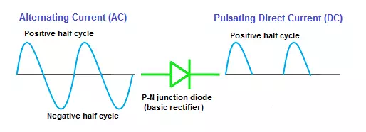
The pulsating direct current is a type of DC current whose value changes over a short period. The pulsating DC current starts from zero and grows to the maximum forward current (peak level), and decreases to zero. However, the pulsating DC current does not change its direction periodically like AC current. The pulsating DC current always flows in one direction like the pure DC current. However, the value of pulsating DC current or pulsating DC voltage slightly changes over a given period. The electric current produced by batteries, power supplies, and solar panels is a pure DC current. By using the combination of components such as capacitors, inductors, and resistors in the circuit, we can achieve the smoothening of pulsating DC to pure DC.
Types of rectifiers
The rectifiers are mainly classified into two types:
- Half wave rectifier
- Full wave rectifier
Half wave rectifier
As the name suggests, the half wave rectifier is a type of rectifier which converts half of the AC input signal (positive half cycle) into pulsating DC output signal and the remaining half signal (negative half cycle) is blocked or lost. In half wave rectifier circuit, we use only a single diode.
Full wave rectifier
The full wave rectifier is a type of rectifier which converts the full AC input signal (positive half cycle and negative half cycle) to pulsating DC output signal. Unlike the half wave rectifier, the input signal is not wasted in full wave rectifier. The efficiency of full wave rectifier is high as compared to the half wave rectifier.