In a Feedback System, all or part of the output signal either positive or negative is fed back to the input
Feedback Systems process signals and as such are signal processors. The processing part of a feedback system may be electrical or electronic, ranging from a very simple to a highly complex circuits. Simple analogue feedback control circuits can be constructed using individual or discrete components, such as transistors, resistors and capacitors, etc, or by using microprocessor-based and integrated circuits (IC’s) to form more complex digital feedback systems. As we have seen, open-loop systems are just that, open ended, and no attempt is made to compensate for changes in circuit conditions or changes in load conditions due to variations in circuit parameters, such as gain and stability, temperature, supply voltage variations and/or external disturbances. But the effects of these “open-loop” variations can be eliminated or at least considerably reduced by the introduction of Feedback.
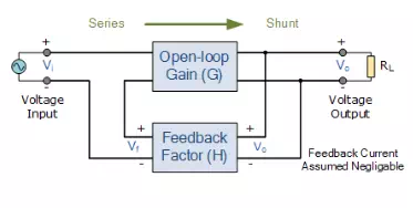
A feedback system is one in which the output signal is sampled and then fed back to the input to form an error signal that drives the system. In the previous tutorial about Closed-loop Systems, we saw that in general, feedback is comprised of a sub-circuit that allows a fraction of the output signal from a system to modify the effective input signal in such a way as to produce a response that can differ substantially from the response produced in the absence of such feedback. Feedback Systems are very useful and widely used in amplifier circuits, oscillators, process control systems as well as other types of electronic systems. But for feedback to be an effective tool it must be controlled as an uncontrolled system will either oscillate or fail to function. The basic model of a feedback system is given as:
Feedback System Block Diagram Model

This basic feedback loop of sensing, controlling and actuation is the main concept behind a feedback control system and there are several good reasons why feedback is applied and used in electronic circuits:
· Circuit characteristics such as the systems gain and response can be precisely controlled.
· Circuit characteristics can be made independent of operating conditions such as supply voltages or temperature variations.
· Signal distortion due to the non-linear nature of the components used can be greatly reduced.
· The Frequency Response, Gain and Bandwidth of a circuit or system can be easily controlled to within tight limits.
Whilst there are many different types of control systems, there are just two main types of feedback control namely: Negative Feedback and Positive Feedback.
Positive Feedback Systems
In a “positive feedback control system”, the set point and output values are added together by the controller as the feedback is “in-phase” with the input. The effect of positive (or regenerative) feedback is to “increase” the systems gain, i.e, the overall gain with positive feedback applied will be greater than the gain without feedback. For example, if someone praises you or gives you positive feedback about something, you feel happy about yourself and are full of energy, you feel more positive. However, in electronic and control systems to much praise and positive feedback can increase the systems gain far too much which would give rise to oscillatory circuit responses as it increases the magnitude of the effective input signal. An example of a positive feedback systems could be an electronic amplifier based on an operational amplifier, or op-amp as shown.
Positive Feedback System
Positive feedback control of the op-amp is achieved by applying a small part of the output voltage signal at Vout back to the non-inverting ( + ) input terminal via the feedback resistor, RF.
If the input voltage Vin is positive, the op-amp amplifies this positive signal and the output becomes more positive. Some of this output voltage is returned back to the input by the feedback network. Thus the input voltage becomes more positive, causing an even larger output voltage and so on. Eventually the output becomes saturated at its positive supply rail.
Likewise, if the input voltage Vin is negative, the reverse happens and the op-amp saturates at its negative supply rail. Then we can see that positive feedback does not allow the circuit to function as an amplifier as the output voltage quickly saturates to one supply rail or the other, because with positive feedback loops “more leads to more” and “less leads to less”. Then if the loop gain is positive for any system the transfer function will be: Av = G / (1 – GH). Note that if GH = 1 the system gain Av = infinity and the circuit will start to self-oscillate, after which no input signal is needed to maintain oscillations, which is useful if you want to make an oscillator. Although often considered undesirable, this behaviour is used in electronics to obtain a very fast switching response to a condition or signal. One example of the use of positive feedback is hysteresis in which a logic device or system maintains a given state until some input crosses a preset threshold. This type of behaviour is called “bi-stability” and is often associated with logic gates and digital switching devices such as multivibrators. We have seen that positive or regenerative feedback increases the gain and the possibility of instability in a system which may lead to self-oscillation and as such, positive feedback is widely used in oscillatory circuits such as Oscillators and Timing circuits.
Negative Feedback Systems
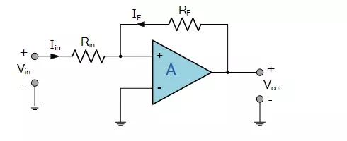
In a “negative feedback control system”, the set point and output values are subtracted from each other as the feedback is “out-of-phase” with the original input. The effect of negative (or degenerative) feedback is to “reduce” the gain. For example, if someone criticises you or gives you negative feedback about something, you feel unhappy about yourself and therefore lack energy, you feel less positive. Because negative feedback produces stable circuit responses, improves stability and increases the operating bandwidth of a given system, the majority of all control and feedback systems is degenerative reducing the effects of the gain. An example of a negative feedback system is an electronic amplifier based on an operational amplifier as shown.
Negative Feedback System

Negative feedback control of the amplifier is achieved by applying a small part of the output voltage signal at Vout back to the inverting ( – ) input terminal via the feedback resistor, Rf.
If the input voltage Vin is positive, the op-amp amplifies this positive signal, but because its connected to the inverting input of the amplifier, and the output becomes more negative. Some of this output voltage is returned back to the input by the feedback network of Rf. Thus the input voltage is reduced by the negative feedback signal, causing an even smaller output voltage and so on. Eventually the output will settle down and become stabilised at a value determined by the gain ratio of Rf ÷ Rin. Likewise, if the input voltage Vin is negative, the reverse happens and the op-amps output becomes positive (inverted) which adds to the negative input signal. Then we can see that negative feedback allows the circuit to function as an amplifier, so long as the output is within the saturation limits. So we can see that the output voltage is stabilised and controlled by the feedback, because with negative feedback loops “more leads to less” and “less leads to more”. Then if the loop gain is positive for any system the transfer function will be: Av = G / (1 + GH).
The use of negative feedback in amplifier and process control systems is widespread because as a rule negative feedback systems are more stable than positive feedback systems, and a negative feedback system is said to be stable if it does not oscillate by itself at any frequency except for a given circuit condition. Another advantage is that negative feedback also makes control systems more immune to random variations in component values and inputs. Of course nothing is for free, so it must be used with caution as negative feedback significantly modifies the operating characteristics of a given system.
Classification of Feedback Systems
Thus far we have seen the way in which the output signal is “fed back” to the input terminal, and for feedback systems this can be of either, Positive Feedback or Negative Feedback. But the manner in which the output signal is measured and introduced into the input circuit can be very different leading to four basic classifications of feedback. Based on the input quantity being amplified, and on the desired output condition, the input and output variables can be modelled as either a voltage or a current. As a result, there are four basic classifications of single-loop feedback system in which the output signal is fed back to the input and these are:
· Series-Shunt Configuration – Voltage in and Voltage out or Voltage Controlled Voltage Source (VCVS).
· Shunt-Shunt Configuration – Current in and Voltage out or Current Controlled Voltage Source (CCVS).
· Series-Series Configuration – Voltage in and Current out or Voltage Controlled Current Source (VCCS).
· Shunt-Series Configuration – Current in and Current out or Current Controlled Current Source (CCCS).
These names come from the way that the feedback network connects between the input and output stages as shown.
Series-Shunt Feedback Systems
Series-Shunt Feedback, also known as series voltage feedback, operates as a voltage-voltage controlled feedback system. The error voltage fed back from the feedback network is in series with the input. The voltage which is fed back from the output being proportional to the output voltage, Vo as it is parallel, or shunt connected.
Series-Shunt Feedback System

For the series-shunt connection, the configuration is defined as the output voltage, Vout to the input voltage, Vin. Most inverting and non-inverting operational amplifier circuits operate with series-shunt feedback producing what is known as a “voltage amplifier”. As a voltage amplifier the ideal input resistance, Rin is very large, and the ideal output resistance, Rout is very small. Then the “series-shunt feedback configuration” works as a true voltage amplifier as the input signal is a voltage and the output signal is a voltage, so the transfer gain is given as: Av = Vout ÷ Vin. Note that this quantity is dimensionless as its units are volts/volts.