(Aluminium or Copper) or .nonmagnetic and nonconducting (bakelite or paint). Inductive transducers meant for such purposes are known as inductive thickness gauges. As the thickness is of primary interest, it is important that the properties of the materials, such as ‘permeability and resistivity, should remain constant. Each gauge is suitably designed for use with the test object and calibrated by making use of reference sheets or slabs of known’ thickness but of the same material of the test object.
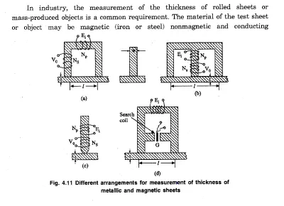
The primary coil of the system shown in fig 4.11 is excited from a relatively high frequency source as the reluctance variation with the thickness of the sample will be very small. However, it is possible to measure variations in the thickness of conducting material sheets. The induced emf of the secondary coil may be used for direct indication and calibration. An alternative is shown in fig 4.11 where the test object of magnetic material forms a ,low reluctance shunt pathforthe magnetic flux across the gap (J. The induced emfs of the search coil serve as the output ‘signals of the transducer-The primary coil is excited from a constant voltage source ofsuitable frequency.


Comments are closed.