VARIABLE RELUCTANCEIN PRESSURE TRANSDUCER
Reluctancein a magnetic circuit is equivalent to resistance in an electrical circuit. Whenever the spacing (or coupling) between the two magnetic devices (or coils) ‘, changes, the reluctance .between ·them also changes. Thus a pressure sensor ‘can- be.. used .to changethe.spacing between two coils by moving one part of the magnetic .circuit. This motion changes’ the reluctance between. the. coils, which in turn changes the voltage induced by one coil in the other. The change in the induced voltage can/then be’ interpreted as a change in pressure.
Construction and. Working
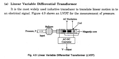
It consists of a primary winding (or coil) and two secondary windings (or coils). The windings are arranged concentrically next to each other. They are wound over a hollow bobbin which is usually of anon-magnetic and insulating materials. A ferromagnetic core (armature) is attached to the transducer sensing shaft (such as’ bellows). The core is generally made of’a high permeability ferromagnetic alloy and has the shape ofa rod or cylinder. A.C excitation is applied across the primary winding and the movable core varies the coupling between it and the two secondary windings. When the core. is in the centre position, the coupling to the secondary coils is equal. As the core moves away from the centre position, .the coupling to one secondary, and hence its output voltage, increases while the coupling and the output voltage of the other secondary decreases.. Any change in pressure. makes the bellows expand’ or contract. This motion moves the magnetic core inside the hollow portion of the bobbin. It causes the voltage. of one secondary winding to increase, while simultaneously reducing the voltage inthe other secondarywinding, The difference ‘of the two voltage appears across the output terminals of the transducers and .gives a measure of the physical position of the core and hence the’ pressure.
Advantages
• It possesses a high sensitivity.
• It has infinite resolution.
• It is very rugged in construction and can usually tolerate ahigh degree of shock & vibration without any adverse effects.
• The .output voltage of this transducer is practically linear for displacements of about 5 mm,
• It shows a low hysteresis, hence repeatability is excellent under a”ll conditions.
• It is stable and easy to align and’ maintain due to simplicity of construction, small size and light body.
Disadvantages
• Temperature affects, the performance of the transducer.
• Relatively large core displacements are required, for appreciable amount of differential output..
(a) Theyare sensitive. to stray magnetic fields ,but shielding is possible.
(b) Servo Pressure Transducer
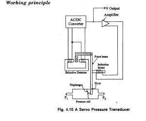
An increase in pressure P1 over P2 (fig 4.10) flexes the diaphragm and moves the short end of the force beam. The force beam pivots,and the long end moves a magnetic .material in the reluctive detector. ‘lbesignal from the reductive detector is converted from a.c power to d.c power, and sent to an amplifier. ‘I’he amplifier responds by activating an inductive motor that moves the force beam back towards its original position. Very little flexing ever occurs in the diaphragm, even over the entire range of the instrument, As a result, the diaphragm lasts along time. Servo pressure transducers are available in a multitude of pressure ranges. The devices are generally used for measurement of pressure below 500 psi. They do not respond to high frequency pressure oscillations. Other servo pressu.re instruments use capacitive detectors, and some use a Bourdon tube as the sensing element.


Comments are closed.