Introduction
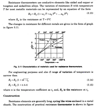
Resistance thermometers are primary’ electrical transducers enabling, measurement of temperature changes .in terms of resistance changes, The’ resistive element is usually made of a solid material, .a metal, metallic alloy or a semiconductor compound. The resistivity’ of metals increases with temperature, while that of semi conductors and insulators generally decreases.
Wire wound elements employ considerable length of wire, and if free to expand, the length also· increases with increase in temperature. Hence astemperature changes, the change in esistance will be due to changes in both length and resistivity. Materials used. for resistance thermometers have temperature coefficient of resistivity much larger than the coefficient of thermal expansion.
Resistance thermometers
RTD Circuits
The variation in resistance is measured and converted into a voltage signal with the help of a bridge circuit – Bridge circuits employ either deflection mode of operation or the null mode. (manually or automatically balance). Figure 3.13 is a bridge for null ~ethod of measurement.
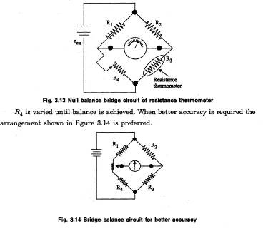
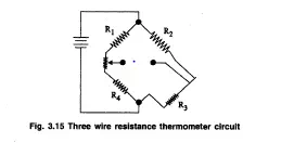
In this circuit the contact resistance in the adjustable resistor has no influence on the resistance of the bridge legs. If long lead wires subjected to temperaturevariations are unavoidablevthen
three wire resistance thermometer is used with the circuit configuration as shown in .figure 3.15.
.Toget a fairly ‘linear relationship. between the output voltage and the temperature, the valuesof R1 and R2 of the above circuits are made atleast 10 times greater than that of the thermometer.
Advantages
• Good Reproducibility
• Fast in response
• Small in size
• High Accuracy
‘. Wide temperature range
• Temperature compensation is not required
Disadvantages
· Cost is high
· Excitation needed
· Large bulb size than thermocouple
· Produce mechanical .vibration.
THERMISTORS:
INDRODUCTION
Thermistorsvare thermal resistors with a .’ .high negative temperature ..coefficientof resistance. They are made of manganese, nickel, copper, iron, uranium and cobalt oxides which were milled, mixed in proper proportions with binders pressed into the desiredshape and sintered.
Construction
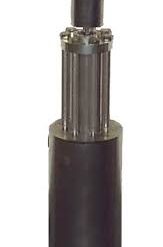
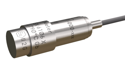
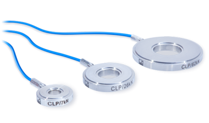
Thermistors are composed of ·sintered mixture of metallic oxides such as manganese, nickel, cobalt, copper, iron and uranium. They are available in variety of sizes and shapes. The thermistors may be in the ‘form of beads, rods and discs. Some of the commercial forms are shown in figure 3.16.
Thermistors.
Thermistor is .a contraction of a term “thermaI resiisstor”.Ther’r·m·stors are generally composed of semi-conductor materials. Although positive temperature co-efficient of’ units (which exhibit an increase in the value of resistance with increase in temperature) are available, most thermistors have /a>negative coefficient of temperature resistance ie. their resistance decreases with increase of temperature. The negativefemperature coefficient of resistance can be as large as several percent per degree ‘celsius. This allows the thermistor circuits
to detect very small changes in temperature which could not be observed with a R’I’D or a th.ermocouple. In some cases the resistance of thermistor at room temperature may decrease as much as 5 percent for each 1°C rise in temperature. This high sensitivity to temperature changes makes thermistors extremely useful for precision temperatur-e measurements control and compenaation. Thermistors are widely used in applicationswhich involve measurements in the range of -60°C to 15°C. The resistance of thermistors ranges from 0.5 Q to 0.75 M Q.Thertnistor is a highly sensitive device. The price to be paid . off for the high sensitivity is in terms of .linearity. The thermistor exhibits a highly non-linear characteristic of resistance versus temperature.
Characteristics of Thermistor Three important characteristics of thermistor make them extremely useful in measurement and control applications. These are:
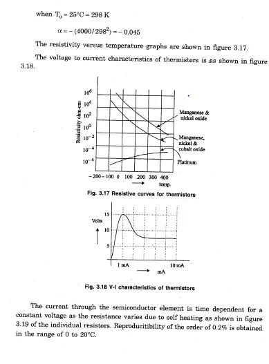
(i) the resistance -‘ temperature characteristics
(ii) the voltage current .characteristics
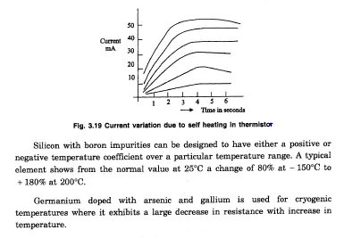
(iii) the ‘current-time characteristics
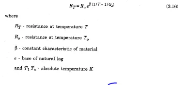
.Thermistors have a large negative temperature coefficient and it is highly nonlinear. The resistance at different temperatures can be found out using the following equation,
Applications
1. Measurement of power at high frequencies.
2. Vacuum measurement.
3.’ Measurement of thermal conductivity.
.·4. Measurement of level, flow and pressure of liquids.
5. Measurement of composition of gases.
Advantages
• Very high sensitivity,
• It can be manufactured in any size ‘or shape.
• Good stability.
• Fast in Response. (In the order of IDS)
Disadvantages
• Highly non-linear.
• In low temperature, sensitivity also low.
• Its upper limit is set by instability.
Temperature Compensation
Because Thermistors have a negative temperature coefficient of resistant opposite to the positive coefficient of most electrical conductors and ‘semiconductors they are widely used to compensate for the effects of temperature on both component and circuit performance. Disk. t~pe thermistors are used for this purpose where the maximum temperature does not exceed± 125°C. A properly selected. thermistor, mounted against or near a circuit element, such asa copper meter coil.. and experiencing the same ambient temperature changes, can be connected in. such a ·\vay that the total circuit resistance is constant. over a wide range of temperatures. This is shown in the curves of figure 3.20 which illustrates the effect of a compensation network.
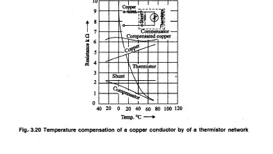
The compensator consists of a thermistor, shunted by a resistor, The negative temperature coefficient of this combination equals the positive coefficient of the copper coil. The coil resistance of 5000 Q at 25°C, varies from approximately 4500 Q at O°Cto 5700 Q.at60°C, representing a change of about ± 12′ percent. With a single thermistor compensation network, this variation is
reduced to about ±15 Q or ±1. / 4 percent. With double or triple compensation networks, variations can be reduced eve


Comments are closed.