INTRODUCTION
Electrical circuits consist of combinations of the three passive elements:
resistor, inductor and capacitor. The primary parameters that describe them are respectively resistance, self or mutual inductance and capacitance. Any change in the parameter of the element can be recognized only when the element is made ‘live’ by electric energization or excitation, otherwise the element is in ‘dead’ state. Hence transducers that are based on the variation of the parameters due to application of any external stimulus are known as passive transducers. In this chapter,resistive, inductive and capacitive transducers are presented
along with the several possibilities available for making use of them for measurement of physical and chemical variables. Wherever possible, ‘sections are subdivided in such a way. as to identify the element of the transducer and the measurand, such as strain-gauge flow transducer and capacitive strain transducer. Basic characteristics of ‘each transducer, its limitations and where necessary, relevant signal processing circuitryare presented. Additional insight is provided for transducers that are more powerful and popular, so as to acquaint the reader with the developments in transducer technology. Though the criteria’ for the design of transducers have been enumerated, details concerning actual designs’ are not given.
Basic -Principle
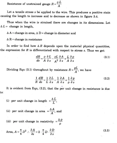
It is generally seen that methods which involve the measurementof change in resistance are preferred to those employing other principles. Thisis because both alternating as well as direct currents and voltages are suitable for resistance ‘measurements. The resistance of a metal cond/uctor is expressed by a simple equation that involves a few physical quantities. The relationship is
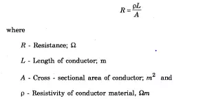
Any method of varying one of the quantities involved in the above relationship can be the design basis of an electrical resistive transducer, There are a number of ways in which resistance can be changed by a physical phenomenon. The translational and rotational potentiometers which work on the basis of change in the value of resistance which change in length of the conductor
can be used for measurement of translational or rotary displacements. Strain gauges work on the principle that the resistance of a conductor or a semi conductor changes when strained. This property can be used for measurement of displacement, force and pressure. The resistivity of materials changes with change of temperature thus causing a change of resistance. This property may be used for measurement of temperature. Thus electrical resistance .transducers have a wide field of application.
POTENTIOMETER
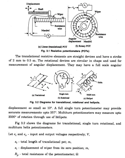
Basically a resistance potentiometer consists of a resistive element provided with a sliding contact. This sliding contact. is called a wiper. The motion of the sliding contact may be translatory or rotational. A linear pot and a-rotary pot are shown in figure 3.1 (a) and (b) respectively. .Some potentiometers use the combination of the two motions, ietranslational as well as rotational. These potentiometers have their resistive element in the’ form of a helix and, therefore, they are called helipots.
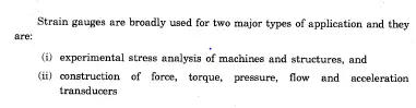
STRAIN GAUGES
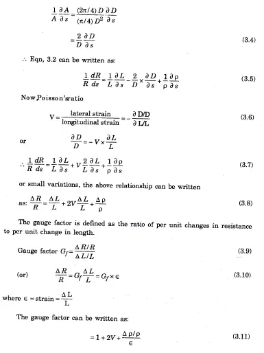
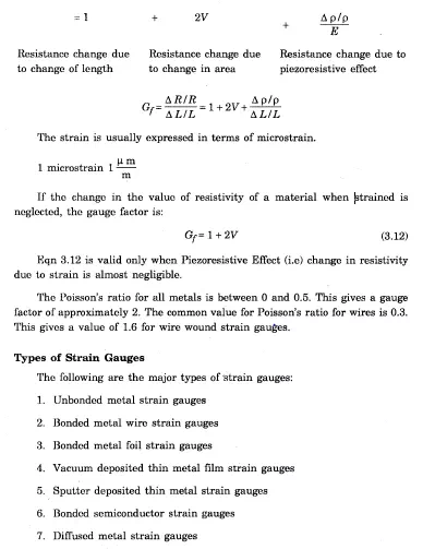
If a metal’ conductor is stretched or compressed, its resistance changes on account of the fact that both length and diameter of conductor change. Also there is a change in the value of resistivity of the conductor when it is strained and this property is called piezoresistiveeffect. Therefore, resistance strain gauges are also known as pie~oresistive gauges. The strainiauges are used for measurement of strain and associated stress in experimental stress analysis. Secondly, many other detectors and transducers, notably-the load. cells, torque ‘meters, diaphragm type pressure gauges, temperature sensors, accelerometers and flow meters employ strain gauges as secondary transducers. Theory of Strain Ga,uges The change in the value of resistance by straining the gauge may be partly explained by the normal dimensional behaviour of elastic material. If a strip of elastic material is subjected to tension, as shown in figure 3.4 or in other words positively strained, its longitudinal dimension will increase while there will be a reduction in the lateral dimension. 80 when a gauge is subjected to a positive strain, its length increases while, its areas of cross-section decreases ‘as shown in Figure 3.4.
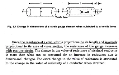
Let us consider a strain gauge made of circular wire. The wire has the dimensions: Length =L, area =A, diameter =D before being strained. The material of the wire has a resistivity p.
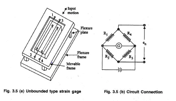
An unbonded metal strain gauge consists of a wire stretched between two points in an insulating medium such as air. It made of various copper nickel chrome nickel or nickel iron alloys. They are about 0.02’5 mm diameter are fixed’ with ,some initial tension between two frames which can move relative to each other. This initial tension or preload is necessary, to avoid buckling under ,compression or negative displacement and this preloading should. be greater than finy expected compression or negative displacement. A simplified figure is shown in figure 3.5.
Unbonded type strain gauge for rotationalmotion is. shown in figure 3.6.
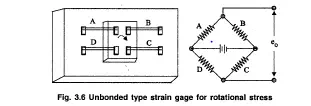
The angular motion gives to the inner member which is pivoted to the outer stationary member, increases the tension on’ the ‘wires and reduces the preload on the. other two wires. For example, clockwise twist given to the centre beam increases the tension on wires A and C and reduces the reloaded tension on wires 13 andD. If’ they are connected .in a bridge as shown then the output voltage available is four times the voltage that would have been obtained due, to a single wire..This .arrangement is useful for measurement of Torsional Strain and angular displacement. This type of gauges can be used to measure only very small displacements of the order of 0.004 cm full scale. Normally these gaugesareu~ed as sensors for force, pressure and acceleration. _In these cases the strain wires serve as’ the necessary spring elements to transduce force to displacement and this displacement is sensed as a resistance variation. The range of force\and deflection values, are decided by the size, length of wires and the number of wires used. The sensitivity for abridge excitation of 5 volts-is 40 mv f1111 scale output for 0.006 em full scale displacement. The nominal value of resistance of the bridge arms is 350 ohms. The thermal sensitivity shift is 0.02% per degree Celsius between – 18°e and 120°0.
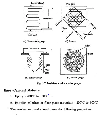
This permits a good transfer of strain from carrier to grid of wires. The wires cannot buckle as they are embedded in a matrix of cement and hence f~ithfullyfollow both the tensile and compressive strains of the specimen. Since, the materials and the wire sizes used for bonded wire strain gauges are the same as used for unbonded wire strain gauges, the gauge factors and resistances for both are comparable..The most commonly used forms of strain gjiuges are shown in figure 8.7. ~ , The nominal values of resistance for these gauges range from 40.’ ,to 2000
ohms, but 120, 350~nd 1000 are common values.
· High dielectric strength
· Minimum temperature restrictions
· Minimum Thickness consistent with other factors
· High mechanical strength
· Good adherence to cements used
Adhesives t Ethylcellulose cement, nitrocellulose cement, bakelite cement and epoxy cement are -some of the commonly used adhesive materials. The temperature range upto which they can be used is usuallybelowLffi’C. Leads The leads should be of such materials which have low and stable resistivity ana also a ‘low resistance temperature coefficient.The recommended lead wire insulation material of the temperature range is:
· Nylon
· Vinyl 65°C to 75°C
· Polyethylene 75°C to 95°C
· Teflon 75°C to 260°0


Comments are closed.