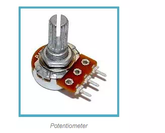
The Potentiometer is an electric instrument that used to measure the EMF (electro motive force) of a given cell, the internal resistance of a cell. And also it is used to compare EMFs of different cells. It can also use as a variable resistor in most of the applications. These potentiometers are used in huge quantities in the manufacture of electronics equipment that provides a way of adjusting electronic circuits so that the correct outputs are obtained. Although their most obvious use must be for volume controls on radios and other electronic equipment used for audio.
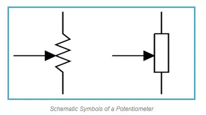
Why is Potentiometer chosen over Voltmeter to measure the potential (EMF) of a cell? When we use Voltmeter, current flows through the circuit and because of the internal resistance of the cell, always terminal potential will be less than the actual cell potential. In this circuit, when the potential difference is balanced (using a Galvanometer null detection), no current flows in the circuit, so the terminal potential will be equal to the actual cell potential. So we can understand that the Voltmeter measures the terminal potential of a cell, but this measures actual cell potential. The schematic symbols of this is shown below.
Construction and Working Principle
The potentiometer consists of a long resistive wire L made up of magnum or with constantan and a battery of known EMF V. This voltage is called as driver cell voltage. Connect the two ends of the resistive wire L to the battery terminals as shown below; let us assume this is a primary circuit arrangement. One terminal of another cell (whose EMF E is to be measured) is at one end of the primary circuit and another end of the cell terminal is connected to any point on the resistive wire through a galvanometer G. Now let us assume this arrangement is a secondary circuit. The arrangement of the potentiometer as shown below.
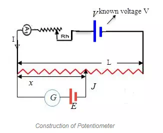
The basic working principle of this is based on the fact that the fall of the potential across any portion of the wire is directly proportional to the length of the wire, provided wire has uniform cross-sectional area and the constant current flowing through it.“When there is no potential difference between any two nodes there is electric current will flow”.
Now the potentiometer wire is actually a wire with high resistivity (ῥ) with uniform cross-sectional area A. Thus, throughout the wire, it has uniform resistance. Now this potentiometer terminal connected to the cell of high EMF V (neglecting its internal resistance) called driver cell or the voltage source. Let the current through the potentiometer is I and R is the total resistance of the potentiometer.
Then by Ohms law V=IR
We know that R= ῥL/A
Thus, V= I ῥL/A
As ῥ and A are always constant and current I is kept constant by a rheostat.
So L ῥ/A=K (constant)
Thus, V= KL. Now suppose a cell E of lower EMF than the driver cell is put in the circuit as shown above. Say it has EMF E. Now in the potentiometer wire say at length x the potentiometer has become E.
E= L ῥx/A=Kx
When this cell be put in the circuit as shown above figure with a jokey connected to the corresponding length (x), there will be no flow of current through the galvanometer because when the potential difference is equal to zero, no current will flow through it. So the galvanometer G show null detection. Then the length (x) is called the length of the null point. Now by knowing the constant K and the length x. We can find the unknown EMF.
E= L ῥx/A=Kx
Secondly, EMF of two cells may also be compared, let the first cell of EMF E1 given a null point at a length= L1 and the second cell of EMF E2 show a null point at length= L2
Then,
E1/E2= L1/L2
Types of Potentiometers
A potentiometer is also commonly known as pot. These potentiometers have three terminal connections. One terminal connected to a sliding contact called wiper and the other two terminals are connected to a fixed resistance track. The wiper can be moved along the resistive track either by use of a linear sliding control or a rotary “wiper” contact. Both rotary and linear controls have the same basic operation.The most common form of the potentiometer is the single turn rotary potentiometer. This type of potentiometer is often used in audio volume control (logarithmic taper) as well as many other applications. Different materials are used to construct potentiometers, including carbon composition, cermet, conductive plastic, and the metal film.
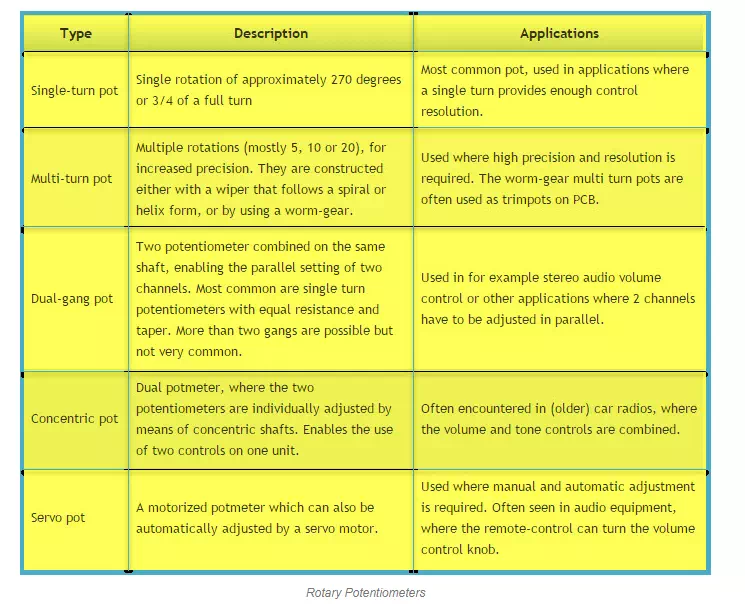
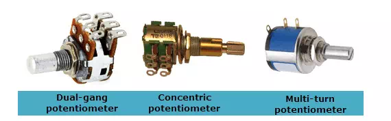
Rotary Potentiometers
These are the most common type of potentiometers, where the wiper moves along a circular path.
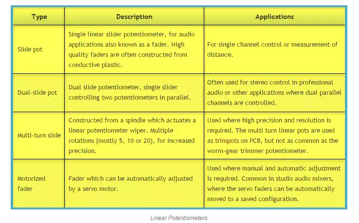
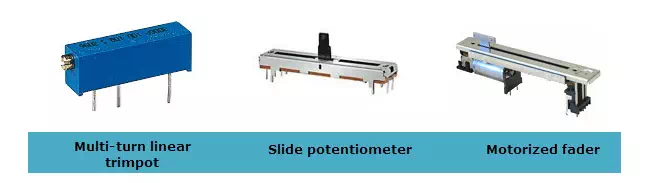
Linear Potentiometers
In these types of Potentiometers the wiper moves along a linear path. Also known as slide pot, slider, or fader.
Applications of Potentiometers
Potentiometer as a Voltage Divider
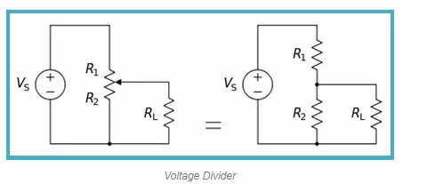
The potentiometer can be worked as a voltage divider to obtain a manual adjustable output voltage at the slider from a fixed input voltage applied across the two ends of the potentiometer. Now the load voltage across RL can be measured as
VL= R2RL. VS/(R1RL+R2RL+R1R2)
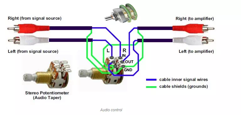
Audio Control
Sliding potentiometers, one of the most common uses for modern low-power potentiometers are as audio control devices. Both sliding pots (faders) and rotary potentiometers (knobs) are regularly used to frequency attenuation, adjust loudness and for different characteristics of audio signals.
Television
Potentiometers were used to control the picture brightness, contrast, and colour response. A potentiometer was often used to adjust “vertical hold”, which affected the synchronization between the received picture signal and the receiver’s internal sweep circuit (a multi-vibrator).
Transducers
One of the most common application is measuring of displacement. To measure the displacement of the body, which is movable, is connected to the sliding element located on the potentiometer. As the body moves, the position of the slider also changes accordingly so the resistance between the fixed point and the slider changes. Due to this the voltage across these points also changes.
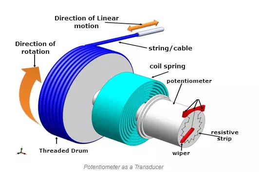
The change in resistance or the voltage is proportional to the change in the displacement of the body. Thus the voltage change indicates the displacement of the body. This can be used for the measurement of translational as well as well rotational displacement. Since these potentiometers work on the principle of resistance, they are also called as the resistive potentiometers. For example, the shaft rotation might represent an angle, and the voltage division ratio can be made proportional to the cosine of the angle. Thus, this is all about types of Potentiometer, its construction and applications. We hope that you have got a better understanding about this information.

Comments are closed.