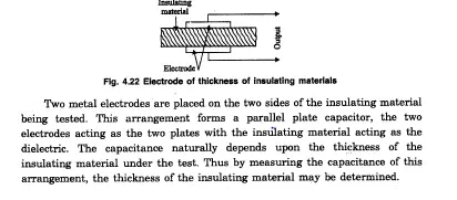
If the material is being tested is an insulator, capacitive method using an arrangement shown in figure 4.22 may be used.
Capacitive’ Strain Transducer
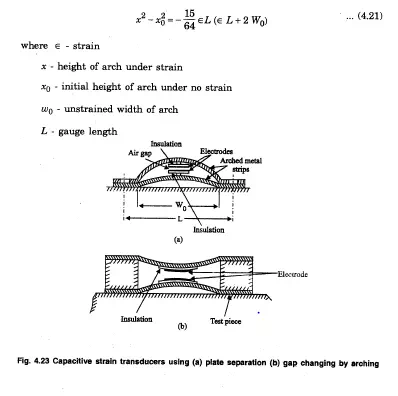
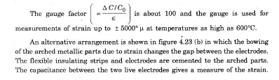
A strain gauge based on the principle of capacitance variation with plate separation is developed making use of two arched metal strips to support the electrodes of the capacitor, as shown in figure 4.2·3 (a). When the structure is strained, there is a .ehange in the differential height- of -the arches as well as the gap between the electrodes. The ‘height variation of ~ach arch strip is
calculated from
Capacitive Pressure Transducer
Differential-pressure can be transduced by a three terminal capacitor as shown in figure 4.24.
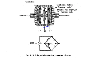
Spherical cavity of a depth of about 0.025 mm is ground in to the glass disk, These depressions are gold coated to form fixed plates of a differential capacitor. A thin stainlesssteel diaphragm is clamped between the disks which _serves as the. movableplate..With equal pressures applied to both parts, the diaphragm is in a neutral position and. the bridge is balanced and eo = O.
If one pressure is greater~t~~n the other the diaphragm deflects to the low pressure side, giving an output eo”in·~proportion to the differential pressure. For the opposite pressure difference. eo exhibits a, 1800 phase change. The high impedance level requires a cathode follower amplifier at eo’ A direction sensitive d.c output can be obtained by conventional phase sensitive’dkmodulation and filtering,