Two coils coupled to each other, such that the orientation of one of them with respect to the other determines the induced emf in one of them, may be used for measurement of angular .deflections over a range of ± 90°. The two coils shown in figure’ 4.2 constitute an equivalent of a transformer with variable coupling between primary and secondary. The mutual-inductance M is maximum when the coils are coaxial, and zero when they are in quadrature. If’O, is the angle between the coil axes, the mutual inductance and the induced emf in the secondary coils are given by
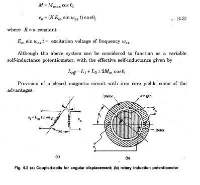
Figure 4.2 (a) shows such an arrangement, with the two coils mounted, one on the stator and oth.er on the rotor. The rotor is usually dumbbell shaped or of any other suitable shape, which, as far as possible, provides uniform gap over the e.ntire periphery. The coils may be concentrated or distributed over the periphery. The concentrated coil system gives an output voltage which is proportional to 8i over a very small range ‘around the null point as seen-from Eq 4.2 (b), where as provision of distributed windings results ~in the extension of the linear range to. ± 90 0
• The devices of this kind belong to the class of induction potentiometers, under the patent names of linvar, indpot, etc. They are normally designed for ‘use at excitation frequencies of 50 Hz ‘Or 400HZ providing sensitivities of the order of’L volt/degree of rotation. The devices are available in different sizes ranging from 10 mm to 75 mm in diameter.