Inductive transducers can. be classified as air cored or iron cored. Air or iron cored coils can be used for inductive transducers. Both have their own advantages and disadvantages.
Air cored coils
Air cored coil transducers can be .operated at a higher carrier frequency because of absence of eddy current losses’ in air cores. The inductance of air cored coils is independent of the current carried by the coil as the permeability of air is constant and does not depend upon the current carried by the coil. Hence air cored coil transducers can be used for measurement of displacement variations occurring at fairly high frequencies.
Iron cored coils·
The greatest ‘disadvantage of iron cored coils transducers is that their .inductance is not constant but .depends upon the value of the current carried by the coil. Also at high frequencies, the eddy current loss tends to be high and therefore iron cored coil transducers cannot. be used beyond a particularfrequency. The frequency of supply voltage should not exceed 20 kHz for iron core transducers to keep the core losses to acceptable values. Hence for accurate measurements the frequency of the input displacement should not exceed 2··kHz.
The advantages of iron cored coil transducers are:
(i) Their size is much smaller-then that air cored transducers on account of high ·permeability of iron cores.
(ii) Iron, cored transducers are less likely to cause external magnetic fields because their magnetic field is confined to the iron core of the transducer on account of high permeability and are less affected by stray magnetic fields on account of the high magnetic field produced by them.
Most .iron cored transducers are of the variable reluctance type where the length of air gap in the magnetic circuit isvaried. In most applications the reluctance of, magnetic circuit is primarily that of air gap.
TRANSDUCERS WORKING ON PRINCIPLE OF PRODUCTION OF EDDY ,CURRENTS
These inductive transducers. work on the principle that if’ aconducting plate is placed .near .a coil carrying alternating current, eddy currents are produced in the conducting plate. The conducting plate acts as a short-circuited secondary winding of a transformer. The eddy currents flowing in the plate produce a magnetic field of their own which acts against the magnetic field produced by the coil. This results in reduction of flux and thus the inductance, of the coil is reduced. The nearer is the plate to the coil, the higher are the eddy currents
and thus higher is, the reduction in the inductance of the coil. Thus the inductance of the coil alters with .variation’ of distance- between the plate and the coil.
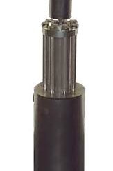
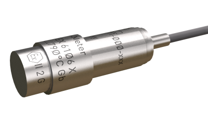
A number of arrangements are possible and two arrangements are shown In, figure 4.1. ‘I’he iplate may’ be at right angle to the axis of the coil. The displacement of the plate causes a change in the inductance of the coil. In the other arrangement a conducting sleeve runs in parallel and coaxially over a coil. If thetshcrt-circuited sleeve is away from the coil, the inductance of the coil is high while if the sleeve is covering the coil, its inductance is low. The change ill inductance is a measure of displacement,