The digital voltmeter (DVM) displays measurements of dc or ac voltages as discrete numerals instead of a pointer deflection on a continuous scale as in analog devices. Numerical readout is advantageous in many applications because it reduces human reading and interpolation errors, eliminates parallax error, increases reading speed, and often provides outputs in digital form suitable for further processing or recording. The DVM is a versatile and accurate instrument that can be used in many laboratory measurement applications. Since the development and perfection DVM have been drastically reduced so that DVMs can actively compete with conventional analog instruments, both in portability and price.
The DVM’s outstanding qualities can best be illustrated by quoting some typical operating and performance characteristics. The following specifications do not all apply to one particular instrument, but they do represent valid information on the present state of the art:
(a) Input range: from ± 1.000000 V to ± 1,000.000 V, with automatic range selection and overload indication
(b) Absolute accuracy: as high as ±0.005 per cent of the reading
(c) Stability: short-term, 0.002 per cent of the reading for a 24-hr period; long-term, 0.008 percent of the reading for a 6-month period
(d) Resolution: 1 part in 106 (1 microV can be read on the 1-V input range)
(e) Input characteristics: input resistance typically 10 Mil; input capacitance typically 40 pF
(f) Calibration: internal calibration standard allows calibration independent of the measuring circuit; derived from stabilized reference source
(g) Output signals: print command allows output to printer; BCD (binary-coded-decimal) output for digital processing or recording
Optional features may include additional circuitry to measure current, resistance, and voltage ratios. Other physical variables may be measured by using suitable transducers.
Digital voltmeters can be classified according to the following broad categories:
(a) Ramp-type DVM
(b) Integrating DVM
(c) Continuous-balance DVM
(d) Successive-approximation DVM
DUAL-SLOPE DVM
The dual-slope type of AtoD conversion is a very popular method for digital voltmeter applications. When compared to other types of analog-to-digital conversion techniques, the dual-slope method is slow but is quite adequate for a digital voltmeter used for laboratory measurements. For data acquisition applications, where a number of measurements are required, faster techniques are recommended. Many refinements have been made to the technique and many large- scale-integration (LSI) chips are available to simplify the construction of DVMs. When a dual-slope AID converter is used for a DVM the counters may be decade rather than binary and the segment and digit drivers may be contained in the chip. When the converter is to interface to a microprocessor, and many high-performance DVMs use microprocessors for data manipulation, the counters employed are binary.
One significant enhancement made to the dual-slope converter is automatic zero correction. As with any analog system, amplifier offset voltages, offset currents, and bias currents can cause errors. In addition, in the dual-slope AtoD converter, the leakage current of the capacitor can cause errors in the integration and consequentially, an error. These effects, in the dual-slope AID converter, will manifest themselves as a reading of the DVM when no input voltage is
present.
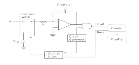
Figure above shows a method of counteracting these effects. The input to the converter is grounded and a capacitor, the auto zero capacitor, is connected via an electronic switch to the output of the integrator. The feedback of the circuitry is such that the voltage at the integrator output is zero. This effectively places an equivalent offset voltage on the automatic zero capacitor so that there is no integration. When the conversion is made, this offset voltage is present to counteract the effects of the input circuitry offset voltages. This automatic zero function is performed before each conversion, so that changes in the offset volt- ages and currents will be compensated.Figure shows a complete dual-slope AID converter.