It is well known that the diodes are expected to be unidirectional devices. These are expected to offer very low resistance for the flow of current under forward biased condition and a very high resistance under reverse bias condition. This important property of the diode can be exploited effectively to test the diode with an intention of knowing whether it is working fine or not. In other words, one can undertake diode testing by measuring the resistance across its terminals by using an equipment like that of multimeter.
Diode Testing Procedure
In this article, we present two methods from which the diode testing can be accomplished. Method 1 This method is to be used when one aspires to test the diode in-hand using analog multimeter.
· Step 1: Set the selector switch of the analog multimeter to its resistance mode.
· Step 2: Connect the negative terminal of the diode to the negative lead (usually black in colour) of the multimeter.
· Step 3: Connect the positive terminal of the diode to the positive lead (usually red in colour) of the multimeter.
- Step 4: Check-out the reading of the multimeter.
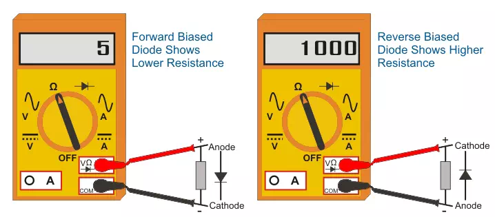
To be Observed: In this case, the multimeter is expected to show a low value. This is because, by following the steps 1 to 4, one would have effectively forward biased the diode – the state in which it should carry current without much loss. Inference: Now, if the reading is not as per the expectation, then the diode is considered to be faulty. On the other hand, if the diode exhibits lesser resistance, then it is to be considered as non-faulty in first-go and one should continue the following steps.
· Step 5: Connect the negative terminal of the diode to the positive lead of the multimeter.
· Step 6: Connect the positive terminal of the diode to the negative lead of the multimeter.
· Step 7: Check-out the reading of the multimeter.
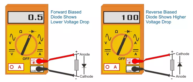
To be Observed: In this case, the multimeter is expected to read a high value of resistance. This is because, now, it would be functioning under reverse biased mode – the mode in which it has to efficiently block the flow of current through it. Inference: If the reading is low, then the diode would be bad while if the reading is high, then it would be a good one. Method 2: In this method, one can check the diode to be good or bad by using a digital multimeter which has a special setting meant for it. This mode can be selected by rotating the mode selector switch of this meter to diode check position. Next, the steps to be followed, observations to be carried-on and the inferences to be arrived-at remain the same as those explained in the previous method. However it is to be noted that, this time the reading shown will be the voltage instead of the resistance.


Comments are closed.