Electrical Network:
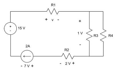
A combination of various electric elements (Resistor, Inductor, Capacitor, Voltage source, Current source) connected in any manner what so ever is called an electrical network. We may classify circuit elements in two categories, passiveand active elements.
Passive Element:
The element which receives energy (or absorbs energy) and then either converts it into heat (R) or stored it in an electric (C) or magnetic (L) field is called passive element.
Active Element:
The elements that supply energy to the circuit is called active element.Examples of active elements include voltage and current sources, generators, and electronic devices that require power supplies. A transistor is an active circuit element, meaning that it can amplify power of a signal. On the other hand, transformer is not an active element because it does not amplify the power level and power remains same both in primary and secondary sides. Transformer is an example of passive element.
Bilateral Element:
Conduction of current in both directions in an element (example: Resistance; Inductance; Capacitance) with same magnitude is termed as bilateral element.

Unilateral Element:
Conduction of current in one direction is termed as unilateral (example: Diode, Transistor) element.

Meaning of Response:
An application of input signal to the system will produce an output signal, the behavior of output signal with time is known as the response of the system.
Potential Energy Difference:
The voltage or potential energy difference between two points in an electric circuit is the amount of energy required to move a unit charge between the two points.
Ohm’sLaw:
Ohm’s law states that the current through a conductor between two points is directly proportional to the potential difference or voltage across the two points, and inversely proportional to the resistance between them. The mathematical equation that describes this relationship is:
I = V / R

where I is the current through the resistance in units of amperes, V is the potential difference measured across the resistance in units of volts, and R is the resistance of the conductor in units of ohms. More specifically, Ohm’s law states that the R in this relation is constant, independent of the current.


