The interconnection of various electric elements in a prescribed manner comprises as an electric circuit in order to perform a desired function. The electric elements include controlled and uncontrolled source of energy, resistors, capacitors, inductors, etc. Analysis of electric circuits refers to computations required to determinethe unknown quantities such as voltage, current and power associated with one or more elements in the circuit. To contribute to the solution of engineering problems one must acquire the basic knowledge of electric circuit analysis and laws. Many other systems, like mechanical, hydraulic, thermal, magnetic and power system are easy to analyze and model by a circuit. To learn how to analyze the models of these systems, first one needs to learn the techniques of circuit analysis. We shall discuss briefly some of the basic circuit elements and the laws that will help us to develop the background of subject.
BASIC ELEMENTS & INTRODUCTORY CONCEPTS:
Electrical Network:
A combination of various electric elements (Resistor, Inductor, Capacitor, Voltage source, Current source) connected in any manner what so ever is called an electrical network. We may classify circuit elements in two categories, passiveand active elements.
Passive Element:
The element which receives energy (or absorbs energy) and then either converts it into heat (R) or stored it in an electric (C) or magnetic (L) field is called passive element.
Active Element:
The elements that supply energy to the circuit is called active element.Examples of active elements include voltage and current sources, generators, and electronic devices that require power supplies. A transistor is an active circuit element, meaning that it can amplify power of a signal. On the other hand, transformer is not an active element because it does not amplify the power level and power remains same both in primary and secondary sides. Transformer is an example of passive element.
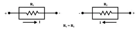
Bilateral Element:
Conduction of current in both directions in an element (example: Resistance; Inductance; Capacitance) with same magnitude is termed as bilateral element.
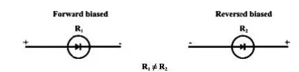
Unilateral Element:
Conduction of current in one direction is termed as unilateral (example: Diode, Transistor) element.
Meaning of Response:
An application of input signal to the system will produce an output signal, the behavior of output signal with time is known as the response of the system.
Potential Energy Difference:
The voltage or potential energy difference between two points in an electric circuit is the amount of energy required to move a unit charge between the two points.
Ohm’sLaw:
Ohm’s law states that the current through a conductor between two points is directly proportional to the potential difference or voltage across the two points, and inversely proportional to the resistance between them. The mathematical equation that describes this relationship is:
I = V / R
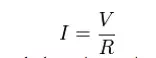
where I is the current through the resistance in units of amperes, V is the potential difference measured across the resistance in units of volts, and R is the resistance of the conductor in units of ohms. More specifically, Ohm’s law states that the R in this relation is constant, independent of the current.
KIRCHOFF’S LAW
Kirchoff’s First Law – The Current Law, (KCL)
“The total current or charge entering a junction or node is exactly equal to the charge leaving the node as it has no other place to go except to leave, as no charge is lost within the node“.
In other words the algebraic sum of ALL the currents entering and leaving a node must be equal to zero,
I(exiting) + I(entering) = 0.
This idea by Kirchoff is known as the Conservation of Charge.
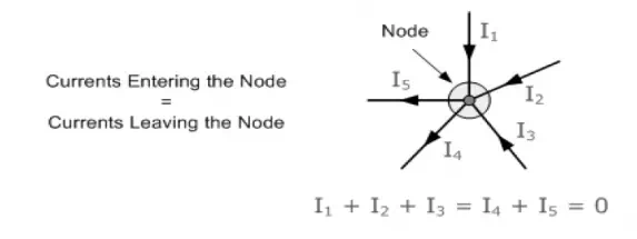
Here, the 3 currents entering the node, I1, I2, I3 are all positive in value and the 2 currents leaving the node, I4 and I5 are negative in value.
Then this means we can also rewrite the equation as; I1 + I2 + I3 – I4 – I5 = 0
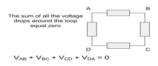
Kirchoff’s Second Law – The Voltage Law, (KVL)
“In any closed loop network, the total voltage around the loop is equal to the sum of allthe voltage drops within the same loop“ which is also equal to zero. In other words the algebraic sum of all voltages within the loop must be equal to zero. This idea by Kirchoff is known as the Conservation of Energy.
Starting at any point in the loop continue in the same direction noting the direction of all the voltage drops, either positive or negative, and returning back to the same starting point. It is important to maintain the same direction either clockwise or anti-clockwise or the final voltage sum will not be equal to zero.
We can use Kirchoff’s voltage law when analyzing series circuits.
Problem 1:
A current of 0.5 A is flowing through the resistance of 10Ω.Findthepotential difference between its ends.
Solution:
Current I = 0.5A.
Resistance R = 10Ω
Potential difference V =?
V = IR
= 0.5 × 10
= 5V.
Problem: 2
A supply voltage of 220V is applied to a resistor100.FindΩthe current flowing through it.
Solution:
Voltage V = 220V Resistance R = 100Ω Current I = V/ R
= 2 2 0 /100
= 2.2 A.
DC CIRCUITS:
A DC circuit (Direct Current circuit) is an electrical circuit that consists of any combination of constant voltage sources, constant current sources, and resistors. In this case, the circuit voltages and currents are constant, i.e., independent of time. More technically, a DC circuit has no memory. That is, a particular circuit voltage or current does not depend on the past value of any circuit voltage or current. This implies that the system of equations that represent a DC circuit do not involve integrals or derivatives.
If a capacitor and/or inductor is added to a DC circuit, the resulting circuit is not, strictly speaking, a DC circuit. However, most such circuits have a DC solution. This solution gives the circuit voltages and currents when the circuit is in DC steady state. More technically, such a circuit is represented by a system of differential equations. The solutions t o t h e s e e q u a t i o n s u s u a l l y c o n t a i n a time varying or transient part as well as constant or steady state part. It is this steady state part that is the DC solution. There are some circuits that do not have a DC solution. Two simple examples are a constant current source connected to a capacitor and a constant voltage source connected to an inductor. In electronics, it is common to refer to a circuit that is powered by a DC voltage source such as a battery or the output of a DC power supply as a DC circuit even though what is meant is that the circuit is DC powered.
AC CIRCUITS:
Fundamentals of AC:
An alternating current (AC) is an electrical current, where the magnitude of the current varies in a cyclical form, as opposed to direct current, where the polarity of the current stays constant.The usual waveform of an AC circuit is generally that of a sine wave, as these results in the most efficient transmission of energy. However in certain applications different waveforms are used, such as triangular or square waves. Used generically, AC refers to the form in which electricity is delivered to businesses and residences. However, audio and radio signals carried on electrical wire are also examples of alternating current. In these applications, an important goal is often the recovery of information encoded (or modulated) onto the AC signal.
DIFFERENCE BETWEEN AC AND DC:
Current that flows continuously in one direction is c a l l e d direct c u r r e n t . Alternating current (A.C) is the current that flows in one direction for a brief time then reverses and flows in opposite direction for a similar time. The source for alternating current is called a.c generator or alternator.
Cycle:
One complete set of positive and negative values of an alternating quantity is called cycle.
Frequency:
The number of cycles made by an alternating quantity per second is called frequency. The unit of frequency is Hertz (Hz)
Amplitude or Peak value:
The maximum positive or negative value of an alternating quantity is called amplitude or peak value.
Average value:
This is the average of instantaneous values of an alternating quantity over one complete cycle of the wave.
Time period:
The time taken to complete one complete cycle.
Average value derivation:
Let i = the instantaneous value of current and i = Im sin ɵ Where, Im is the maximum value.
Resistors in series and parallel circuits:
Series circuits:
Figure shows three resistors R1, R2 and R3 connected end to end, i.e. in series, with a battery source of V volts. Since the circuit is closed a current I will flow and the p.d. across each resistor may be determined from the voltmeter readings V1, V2 and V3
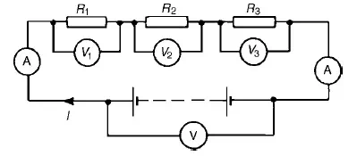
In a series circuit
(a) the current I is the same in all parts of the circuit and hence the same reading is found on each of the two ammeters shown, and
(b)the sum of the voltages V1, V2 and V3 is equal to the total applied voltage, V, i.e.
V = V1 +V2 +V3
From Ohm’s law:
V1 = IR1, V2 = IR2, V3 = IR3 and V = IR where R is the total circuit resistance. Since V =V1 + V2 + V3
then IR =IR1 + IR2 + IR3 Dividing throughout by I gives R = R1 + R2 + R3 Thus for a series circuit, the total resistance is obtained by adding together the values of the separate resistances.
Problem 1: For the circuit shown in Figure 5.2, determine (a) the battery voltage V, (b) the totalresistance of the circuit, and (c) the values of resistance of resistors R1, R2 and R3, given that the p.d.’sR1, R2acrossandR3are5V, 2V and 6V respectively.
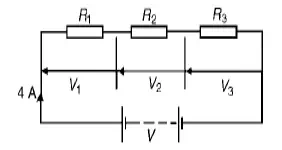
(a) Battery voltage V =V1 + V2 + V3 =5 + 2 + 6=13V
(b)Total circuit resistance R= V/ I
= 13/4=3.25Ω
(c) Resistance R1 = V1/ I
= 5/4
=1.25 Ω Resistance R2 = V2/ I
= 2/4 =0.5 Ω
Resistance R3 = V3/ I = 6/4 =1.5 Ω
Problem 2. For the circuit shown in Figure determine the p.d. across resistorR3. If the totalresistance of the circuit is 100_, determine the current flowing through resistor R1. Find also the value of resistor R2.
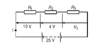
P.d. across R3, V3 =25 −10 −4=11V Current I = V/ R
= 25/100
=0.25A, which is the current flowing in each resistor Resistance R2 = V2/ I
= 4/0.25 =16 Ω
Problem 3: A 12V battery is connected in a circuit having three series-connected resistors havingresistances of 4 Ω, 9 Ωand 11 Ω. Determine the current flowing through, and the p.d. across the 9 Ωresistor. Find also the power dissipated in the 11 Ωresistor.
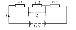
Total resistance R=4 + 9 + 11=24 Ω Current I = V/ R
= 12/24
=0.5A, which is the current in the 9 Ωresistor. P.d. across the 9_ resistor, V1 = I × 9 = 0.5 × 9
= 4.5V
Power dissipated in the 11 Ωresistor, P = I2R=0.52(11)
= 0.25(11)
= 2.75W
PARALLEL NETWORKS:
Problem 1: Figure shows three resistors, R1, R2 and R3 connected across each other, i.e. inparallel, across a battery source
of V volts.
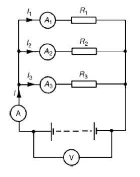
In a parallel circuit:
(a) the sum of the currents I1, I2 and I3 is equal to the total circuit current, I, i.e. I =I1 +I2 +I3, and the source p.d., V volts, is the same across each of the From Ohm’s law:
I1 = V/R1 , I2 = V/R2 , I3 = V/R3 and I = V/R where R is the total circuit resistance. Since I =I1 + I2 + I3 then
V/R= V/R1+ V/R2+ V/R3 Dividing throughout by V gives:
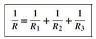
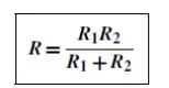
This equation must be used when finding the total resistance R of a parallel circuit. For the special case of two resistors in parallel
Problem 2: For the circuit shown in Figure , determine (a) the reading on the ammeter, and (b) thevalue of resistor R2.
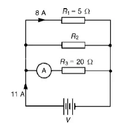
P.d. across R1 is the same as the supply voltage V.
Hence supply voltage, V =8 × 5=40V
(a) Reading on ammeter, I = V R3= 40/20=2A
Current flowing through R2 =11−8−2=1A
Hence, R2 = V/I2= 40/1=40 Ω
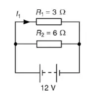
(a) The total circuit resistance R is given by 1/R= 1/R1+ 1/R2= 1/3+ 1/6
1/R= 2 + 1/6= 3/6 Hence, R = 6/3= 2 Ω
(b) Current in the 3 Ωresistance, I1 = V R1= 12/3= 4A
Problem 3: For the circuit shown in Figure find (a) the value of the supply voltage V and (b) thevalue of current I.
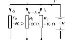
(a) P.d. across 20 Ωresistor = I2R2 = 3× 20 = 60V, hence supply voltage V =60V since the circuit is connected in parallel.
(b)Current I1 = V/R1= 60/10= 6A; I2 = 3A
I3 = V/R3= 60/60= 1A
Current I =I1+I2+I3 and hence I =6+3+1=10A Alternatively,
1/R= 1/60+ 1/20+ 1/10= 1 + 3 + 6/60= 10/60 Hence total resistance R= 6010=6 Ω Current I = V/R= 60/6=10A
Problem 4: Find the equivalent resistance for the circuit shown in Figure
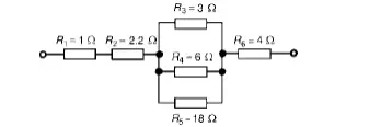
R3, R4 andR5 are connected in parallel and their equivalent resistance R is given by:1/R= 1/3+ 1/6+ 1/18=6 + 3 + 1/18= 10/18
Hence R= 18/10=1.8 Ω
The circuit is now equivalent to four resistors in series and the equivalent circuit resistance =1+2.2+1.8+4=9 Ω
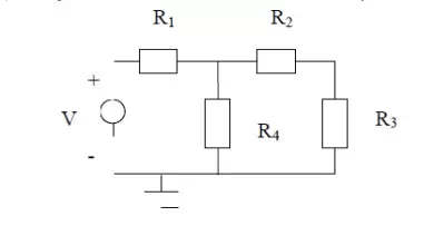
MESH ANALYSIS:
This is an alternative structured approach to solving the circuit and is based on calculating mesh currents. A similar approach to the node situation is used. A set of equations (based on KVL for each mesh) is formed and the equations are solved for unknown values. As many equations are needed as unknown mesh currents exist.
Step 1: Identify the mesh currents
Step 2: Determine which mesh currents are known
Step 2: Write equation for each mesh using KVL and that includes the mesh currents Step 3: Solve the equations
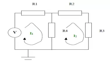
Step 1:
The mesh currents are as shown in the diagram on the next page
Step 2:
Neither of the mesh currents is known
Step 3:
KVL can be applied to the left hand side loop. This states the voltages around the loop sum to zero.
When writing down the voltages across each resistor equations are the mesh currents.
I1R1 + (I1 – I2) R4 – V = 0
KVL can be applied to the right hand side loop. This states the voltages around the loop sum to zero. When writing down the voltages across ea the equations are the mesh currents.
I2R2 + I2R3 + (I2 – I1) R4 = 0
Step 4:
Solving the equations we get
The individual branch currents can be obtained from the these mesh currents and the node voltages can also be calculated using this information. For example:
Problem 1:
Use mesh-current analysis to determine the current flowing in (a the 1Ω resistance of the d.c. circuit shown in
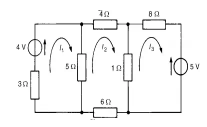
The mesh currents I1, I2 and I3 are shown in Figure
Using Kirchhoff’s voltage law:
For loop 1, (3 + 5) I1 −I2 = 4 …………………………………………………………(1)
For loop 2, (4 + 1 + 6 + 5) I2 −(5) I1 −(1) I3 = 0…………………………………….(2)
For loop 3, (1 + 8) I3 −(1) I2 = 5− ……………………………………………………(3)
Thus
8I1 −5I2 −4 =0
−5I1 + 16I2 −I3 =0
−I2 + 9I3 + 5 =0
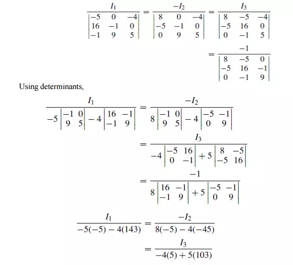
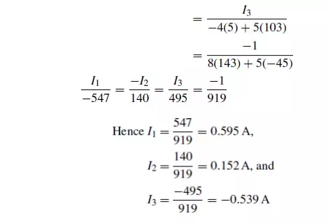
(a) Current in the 5 Ωresistance = I1 −I2
= 0.595 −0.152
= 0.44A
(b) Current in the 1 Ωresistance = I2 −I3
= 0.152 −(−0.539)
= 0.69A
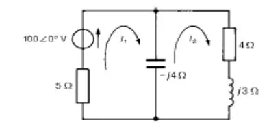
Problem 2: For the a.c. network shown in Figure determine, using mesh-current analysis, (a) themesh currents I1 and I2 (b) the current flowing in the capacitor, and (c) the active power delivered by the 100∠0◦V voltage source.
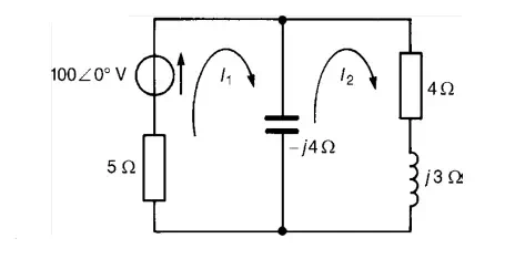
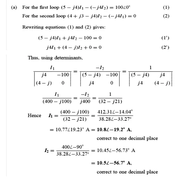
(a) For the first loop
(5−j4) I1 −(−j4I2) =100∠0◦……………………………………………………(1) For the second loop
(4+j3−j4)I2 −(−j4I1) =0 ……………………………………………………… (2)
Rewriting equations (1) and (2) gives:
(5 −j4)I1 + j4I2 −100 =0
j4I1 + (4 −j) I2 + 0 =0 Thus, using determinants,
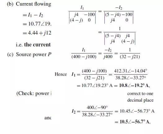
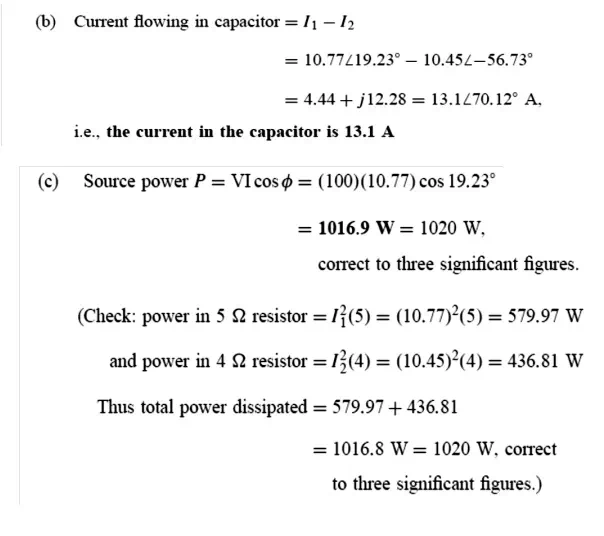
Thus total power dissipated = 579.97 + 436.81 = 1016.8W = 1020W
Problem 3: Calculate current through-6Ω resistance u
Case(1): Consider loop ABGH ; Apply KVL .
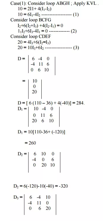
D3 = 6(220) +4(-80) +10(-24)
D3 = 760
I1 = D1/D = 260/284 = 0.915A
I2 = D2/D = -320/284 = -1.1267A I3 = D3/D = 760/284 = 2.676A
Current through 6Ω 2 +Iresistance3 = I
= -1.1267+2.676 = 1.55A
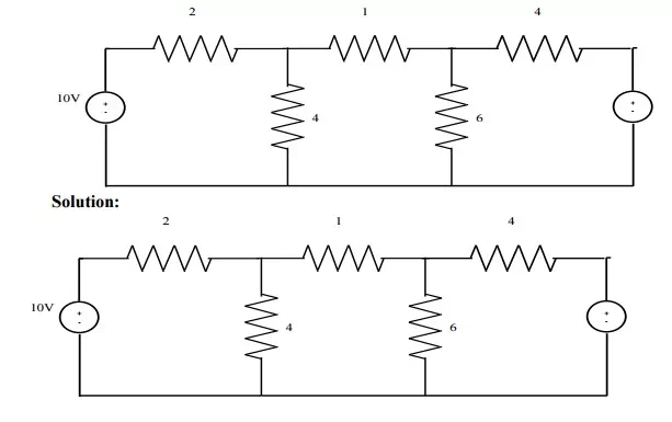
Problem 4: Find the current through branch a-b using mesh analysis.
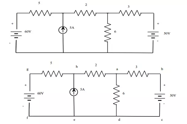
Solution
Consider loops
Loop HADE – > 5I1+2I2+6(I2-I3) = 60
5I1+8I2-6I3 = 60 ———— (1)
Loop ABCDA – > 3I3+6(I3-I2) = -50
3I3+6I3-6I2 = -50
9I3-6I2 = -50———- (2)
I2-I1 = 5A ————————- (3)
From (1), (2) & (3).
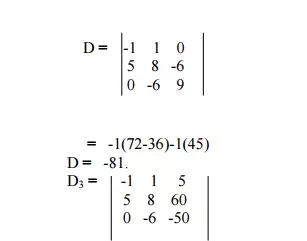
= -1(-400+360)-(-250) +5(-30)
= 40+250-150
D3 = 140.
I3 = D3/D = 140/-81 = -1.7283
The current through branch ab is 1.7283A which is flowing from b to a.
NODAL ANALYSIS:
Nodal analysis involves looking at a circuit and determining all the node voltages in the circuit. The voltage at any given node of a circuit is the voltage drop between that node and a reference node (usually ground). Once the node voltages are known any of the currents flowing in the circuit can be determined. The node method offers an organized way of achieving this.
Approach:
Firstly all the nodes in the circuited are counted and identified. Secondly nodes at which the voltage is already known are listed. A set of equations based on the node voltages are formed and these equations are solved for unknown quantities. The set of equations are formed using KCL at each node. The set of simultaneous equations that is produced is then solved. Branch currents can then be found once the node voltages are known. This can be reduced to a series of steps:
Step 1: Identify the nodes
Step 2: Choose a reference node
Step 3: Identify which node voltages are known if any Step 4: Identify the BRANCH currents
Step 5: Use KCL to write an equation for each unknown node voltage Step 6: Solve the equations
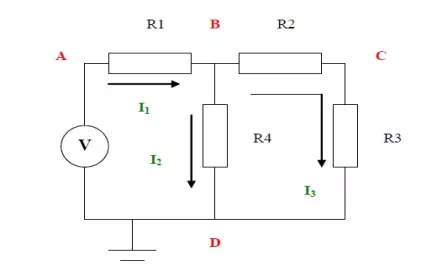
This is best illustrated with an example. Find all currents and voltages in the following circuit using the node method. (In this particular case it can be solved in other ways as well)
Step 1:
There are four nodes in the circuit. A, B, C and D
Step 2:
Ground, node D is the reference node.
Step 3:
Node voltage B and C are unknown. Voltage at A is V and at D is 0
Step 4:
The currents are as shown. There are 3 different currents
Step 5:
I need to create two equations so I apply KCL at node B and node C
The statement of KCL for node B is as follows:
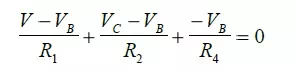
The statement of KCL for node C is as follows:
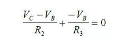
Step 6:
We now have two equations to solve for the two unknowns VB and VC. Solving the above two equations we get:
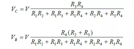
Further Calculations
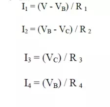
The node voltages are know all known. From these we can get the branch currents by a simple application of Ohm’s Law:
Problem 1: Find the current through each resistor of the circuit shown in fig, using nodalanalysis
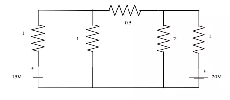
Solution:
At node1,
-I1-I2-I3 = 0 -[V1-15/1]-[V1/1][V1-V2/0.5] = 0
-V1+15-V1-2V1+2V2 = 0
4V1-2V2 = 15 ——————— (1)
At node2,
I3-I4-I5 = 0
V1-V2/0.5 –V2/2 –V2-20/1 = 0
2V1-2V2-0.5V2-V2 + 20 = 0
2V1-3.5V2 = -20 —————— (2)
Multiplying (2) by 2 & subtracting from (1)
5V2 = 55 V2 = 11V V = 9.25V
I1 = V1-5/1 = 9.25-15 = -5.75A = 5.75 I2 = V1/1 = 9.25A
I3 = V1-V2/0.5 = -3.5A = 3.5A ß I4 = V2/2 = 5.5A
I5 = V2-20/I = 11-20/1 = -9A=9A.
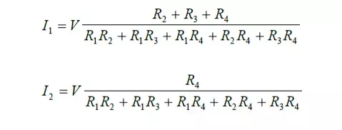
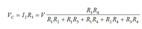
Problem 2: For the bridge network shown in Figure determine the currents in each of the resistors.
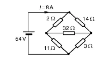
Let the current in the 2 resistor be I1, and thens currentby law,Kirchhoff’thecurrentinthe14 resistor is (I -I1). Let the current in the 32 resistor be I2 as shown in Figure Then the current in the 11 resistor is (I1 – I2) and that in the 3 resistor is (I – I1 + I2). Applying Kirchhoff’s and moving in a clockwise direction as shown in Figure gives:
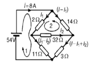
54 = 2I1 +11(I1 _-I2)
i.e. 13I1 – 11I2 = 54
Applying Kirchhoff’s voltage law to loop 2 and direction as shown in Figure gives:
0 = 2I1 + 32I2 -14(I – I1)
However I = 8 A
Hence 0 = 2I1 + 32I2 –14(8 -_I1) i.e. 16I1 + 32I2 = 112
Equations (1) and (2) are simultaneous equations with two unknowns, I1 and I2.
16 * (1) gives: 208I1 _-176I2 = 864
16 * (1) gives: 208I1 _-176I2 = 864
13 * (2) gives: 208I1 + 416I2 = 1456
(4) – (3) gives: 592I2 = 592, I2 = 1 A
Substituting for I2 in (1) gives:
13I1 – 11 = 54
I1 = 65/13 = 5 A
Hence,
the current flowing in the 2 resistor = I1 = 5 A
the current flowing in the 14 resistor = I -I1 = 8 -5 = 3 A
the current flowing in the 32 resistor = I2 = 1 A
the current flowing in the 11 resistor = I1 – I2 = 5 -1 = 4 A and
the current flowing in the 3 resistor = I – I1 + I2 = 8 – 5 + 1 = 4 A
Problem 3: Determine the values of currents I, I1 and I2 shown in the network of Figure
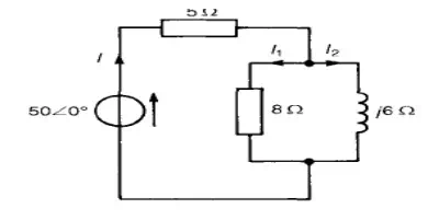
Total circuit impedance,
ZT = 5 + (8)(j6)/8 + j6
= 5 + (j48)(8 – j6)/82 + 62
= 5 + (j384 + 288)/100
= (7.88 + j3.84) or 8.776 25.98° A Current I = V/ZT
= 50∟ 0°/8.77∟ 25.98°
= 5.7066 −25.98° A
Current I1 = I (j6/8 + j6)
= (5.702∟5.98°) (6∟ 90°)/10∟ 36.87°
= 3.426∟27.15° A
Current I2 = I (8/ (8 + j6)
= (5-.2570∟.98°)*8∟ 0°/10∟ 36.87°
= 4.5666 −62.85° A
[Note: I = I1 + I2-62.=85° 3.42 ∟27.15° + 4.56∟
= 3.043 + j1.561 + 2.081 – j4.058
= 5.124 – j2.497 A = 5.706 -25.98° A
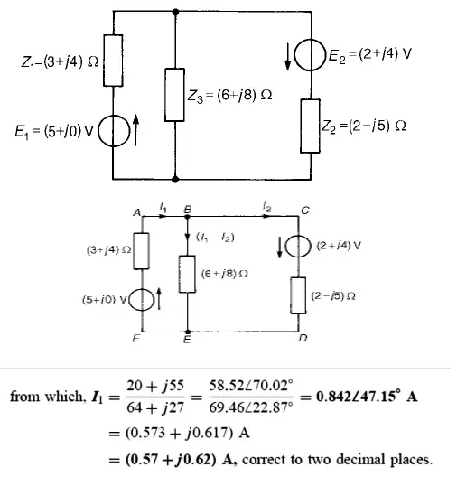
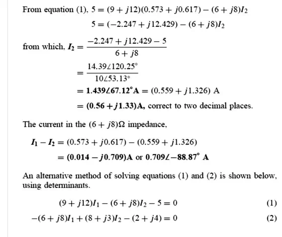
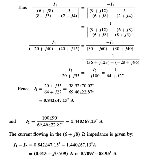
Problem 4: For the a.c. network shown in Figure, determine the current flowing in each branchusing Kirchhoff’s laws.
Problem 5: For the a.c. network shown in Figure determine, using mesh-current analysis, (a) themesh currents I1 and I2 (b) the current flowing in the capacitor, and (c) the active power delivered by the 1006 0° V voltage source.
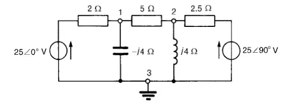
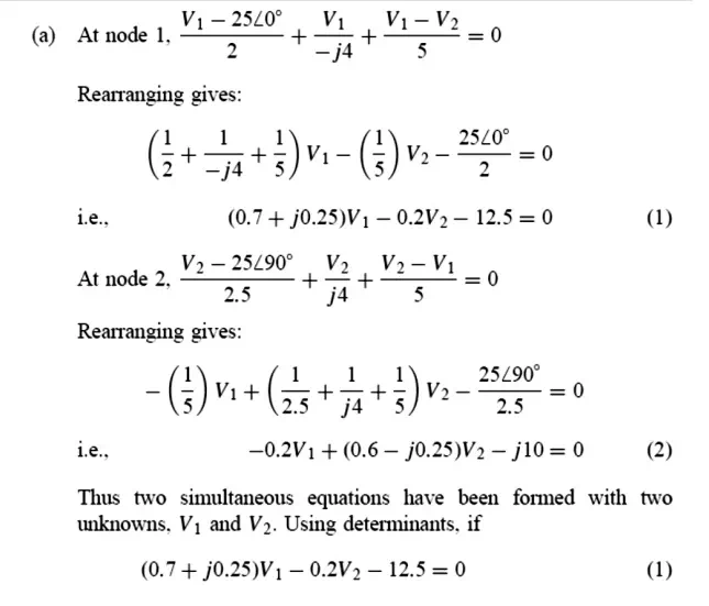
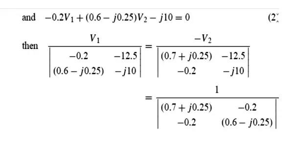
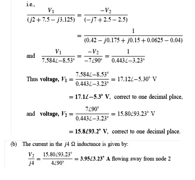
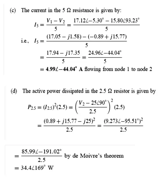
Problem 6: In the network of Figure use nodal analysis to determine (a) the voltage at nodes 1 and 2, (b) the current in the j4 Ω inductance, (c) of the active power dissipated-10) in the 2.5 Ω