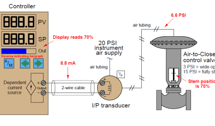
A DCS, PLC, single-loop controller or other device analog input accepts an electronic signal, such as 4 to 20 mA or 1 to 5 VDC, and converts it to a digital value.
When a 4 to 20 mA signal is said to be accepted by an analog input module or card, it does not actually measure the current direction in most cases.
Most analogue inputs measure the current by measuring the resulting voltage drop over a resistor, typically a resistor of 250 ohm.
A typical process transmitter is a combination of a transducer, a translation circuit and a source of variable current. One measurable parameter is converted into another measurable parameter by a transducer.
Example:

The sensed pressure pushes on the sensing diaphragm, which is one of the plates in a capacitor. A condenser’s capacitance value changes as the distance between the plates changes, causing a change in the oscillator circuit frequency.
The translation circuitry adjusts the non-linearity of the transducer, the temperature variations and other factors to ensure that the 4 to 20 mA signal is accurate, repeatable and as linear as possible (in most cases)
There are three types of transmitter connection:
2-Wire Transmitters:
Most analog inputs have a precision resistor of 250 ohm to convert the current signal from 4 to 20 mA to a voltage signal from 1 to 5 V. The loop power supply could be provided for a 2-wire transmitter loop inside the control system or outside the control system.

Loop Power Supply Internal to Control System

Loop Power Supply External to Control System
3-Wire Transmitters:
Three-wire transmitters require a third wire to provide the transmitter with sufficient operating current (over 20 mA) to function properly.
Typically, this third wire provides the same voltage as the loop power supply such as 24 VDC and carries the total current required for the operation of the device and the loop current.

4-Wire Transmitters:
Typically, four wire transmitters require 120 VAC or 230 VAC to power the internal circuitry and internal loop power supply of the transmitter.
It is called 4-wire because it has two wires for the loop and two wires for power (the ground conductor being ignored for the AC power).


